
CHAPTER 3: An Introduction to Vacuum Systems
3.3 Throughput, Pumping Speed and Conductance
3.4 Vacuum Systems – An Overview
3.4.4 Vacuum System Components
3.5 Schematic Symbols and Diagrams
3.6 A Simple Rough Vacuum System
Chapter 3 describes the general operating conditions associated with the function of a vacuum system and the types of components used in the design of these systems. After you read this chapter, you will be able to:
- Identify the sources that contribute to gas load in rough and high vacuum regimes.
- Calculate the gas load of the bulk gas present in a vacuum chamber before initiating a system pumpdown.
- Describe the terms “throughput”, “pumping speed” and “conductance” and explain the relationship between these terms.
- Calculate the net pumping speed at the outlet of a vacuum chamber given the pumping speed and conductance.
- Identify the main components present in a vacuum system.
- Calculate an estimated gas load associated with the outgassing of the vacuum chamber material given the outgassing rate of the chamber material and the dimensions of the chamber.
- Identify and classify the types of vacuum pumps suitable for use in the rough vacuum and high vacuum regimes.
- Identify and classify the types of gauges suitable for use in the rough vacuum and high vacuum regimes.
- List and describe other components used in the design of vacuum systems.
- Draw a schematic diagram of a basic vacuum system using symbols commonly used to represent vacuum system components.
3.1 Introduction
In Chapter 1, we learned that vacuum technology is used to intentionally create a volume with a lower density of gas molecules than the atmospheric conditions surrounding it. Vacuum pressure conditions enable a variety of processes. In other words, a sub-atmospheric operating condition makes it possible to create and manufacture useful products or do scientific research. Different processes require different levels of vacuum. In Chapter 1, Table 1.1 listed examples of different processes that depend on vacuum and sorted them according to the vacuum regime in which they take place.
In Chapter 2, we reviewed some of the science that explains the behavior of gases. The kinetic theory of gases is the foundation for understanding properties of gases, including the ideal gas law and the special cases that arise from it. The kinetic theory of gases also addresses characteristics of molecular motion. We discussed how as the pressure is decreased below atmospheric pressure, the distance a molecule travels before colliding with another molecule, its free path, increases. The mean free path, the average of the distances between molecule-to-molecule collisions, is related to the pressure. Processes designed to be carried out under vacuum focus on controlling the types and amounts of gas molecules present to achieve a suitable mean free path.
With this background, we can begin to address the foundations of vacuum system installation, operation, maintenance, and troubleshooting. This chapter begins with a discussion of gas load, that is, the amount of gas that has to be removed from the chamber. Contributions to the gas load in a vacuum system come from many different sources. In each pressure regime, certain sources of gas molecules play a bigger role in contributing to the gas load than others. The design of a vacuum system is tailored to the process it supports including how to address the gas load.
Next, we will look at ways to describe, quantitatively and physically, how a vacuum system functions. In its simplest form, a vacuum system consists of a volume, the chamber, connected to a vacuum pump. The vacuum pump is the active mechanism used to remove gases from the chamber. Ideally, vacuum system design would be a simple activity with the only consideration being what vacuum pump will most quickly remove gases from the chamber. The reality of functional vacuum system design is much more complex. The issue that drives the level of complexity is the changing composition of the gas load and the underlying motion of the gas molecules, especially as the molecular density decreases within the vacuum system. We will introduce the interrelated concepts of throughput, pumping speed and conductance. Throughput, pumping speed and conductance are quantities used to represent the ability of the vacuum system to remove gas molecules from the system.
We will introduce and provide an overview of the various components found in vacuum systems. Component selection is tied to what operating pressure is required by the process and the conditions necessary to achieve that operating pressure. Individual components and the condition of those components can significantly impact a vacuum system’s performance. Individuals who install components, troubleshoot, or perform routine maintenance activities on a vacuum system need to be aware of and anticipate component-related issues as they perform these activities. We conclude this chapter with a description of a very simple vacuum system including a schematic drawing used to represent this simple vacuum system.
The purpose of this chapter is to set the stage for Chapters 4 and 5. As we study the rough and high-vacuum pressure regimes, we will approach each regime in the same manner. First, the gas load in the given pressure regime will be described. Then the different pumping mechanisms that can be used to remove gas molecules from the chamber and appropriate pressure gauges will be presented. A short discussion of valves and fittings will follow, and the chapter will close with system characterization and troubleshooting. So, let’s begin.
3.2 Gas Loads
A vacuum system functions to first remove gas from the chamber environment and then to maintain a certain pressure to support a desired process. The vacuum system has to deal with a gas load that changes as pressure in the system decreases. Gas load is defined as the rate at which gas molecules from various sources enter into the vacuum system. At any point in time, the total gas load reflects the sum of all these rates from the contributing gas sources. The composition of the gas load in a vacuum system is not only the volume gas in the chamber but also depends on the types of components and associated materials used to construct the system, the presence and relative amount of water vapor, and the constituents and by-products of the process being performed. Although vacuum systems can be designed to achieve extremely low-pressure conditions, it is impossible to eliminate the gas load entirely.
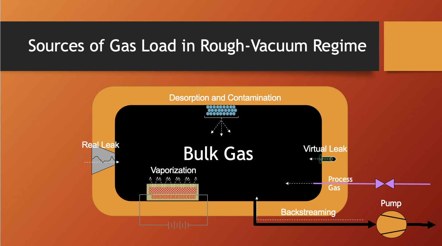
Let us consider some of these contributing gas sources (see Figure 3.1). In the rough-vacuum regime, the major contributor to gas load is the volume gas, also called the bulk gas. The bulk gas is the gas that originally fills the chamber. Using the ideal gas law, we can predict the amount of bulk gas present by multiplying the pressure in the chamber by the chamber volume. Therefore, the larger the chamber, the greater the amount of bulk gas that needs to be removed from the chamber. Every vacuum system, if it has been opened to the atmosphere, begins at approximately 1 atmosphere (atm), or 760 Torr pressure at sea level. The gas load at this point predominantly consists of air as the bulk gas. So, if the chamber volume is 10 liters and the pressure is 760 Torr, the gas load in the chamber due to the bulk gas is 760 Torr x 10 liters, or 7600 Torr-liters.
For a cylindrical chamber with an inner diameter of 170 mm and a height of 230 mm, calculate the approximate gas load in a chamber due to the bulk gas. Assume this chamber is located in Salt Lake City, Utah.
Solution:
The initial contribution of the bulk gas to the gas load is the volume of the chamber multiplied by atmospheric pressure.
In this particular example, it is important to recognize that location, specifically the location’s altitude, affects the level of atmospheric pressure to assume. Salt Lake City, Utah is at an altitude much greater than sea level. The nominal atmospheric pressure condition in Salt Lake City is approximately 640 Torr.
Calculate the volume of this chamber.
Substituting 170 mm for d and 230 mm for h,
Convert units of mm3 to units of cm3,
One cm3 is equal to 1 milliliter (ml). One liter is equal to 1,000 ml.
So, if the volume of the chamber is 5.2 liters and the pressure is 640 Torr, the gas load due to the bulk gas is 640 Torr times 5.2 liters, or 3,328 Torr-liters.
As the chamber is pumped down and most of the bulk gas is removed, the pressure drops reflecting the decreasing gas load in the fixed volume of the chamber. At the low end of the rough-vacuum regime, the bulk gas no longer is the major contributor to gas load and other gas (vapor) sources now take greater significance. For example, water vapor desorbing from the chamber walls now becomes a significant contributor.
In the high-vacuum regime, other sources of gas become noticeable since the dominant gas sources that contributed to gas load in the rough-vacuum regime have been removed (see Figure 3.2). Outgassing and permeation now become significant contributors to gas load. Outgassing refers to the escape of gas molecules that are condensed onto and within solid materials, for example, the chamber wall material and any other solids placed in the chamber, and enter into the gas load within the chamber. Permeation is a process in which gas molecules pass through materials used in the construction of vacuum systems, such as the elastomer O-ring seals in the flanges that connect vacuum components.

Contributions to gas load due to leaks can be caused by real leaks or virtual leaks. Leaks can occur in any of the vacuum regimes. In life, we have all experienced real leaks, except the gas is usually flowing from inside to outside, like a bicycle tire that has a puncture. In a vacuum system, a real leak provides a path for air molecules to travel from outside the chamber to inside the chamber through a space in the chamber wall or through a faulty connection in the vacuum system. In contrast, virtual leaks are not true leaks, but they act in a similar manner, adding to the gas load. Virtual leaks are amounts of trapped gas molecules that escape slowly as pressure decreases in the chamber. An example might be the gas trapped between the threads of a screw in the interior of the chamber.
And finally, when a process is being run, the process chamber is first pumped down to the desired pressure, and process gases are fed into the chamber at a specific flow rate. Some of the process gases react in the chamber, producing not only the desired material but also reaction by-products. Reaction by-products and any unreacted process gas molecules add to the gas load and must be removed from the chamber.
We will examine gas loads in more detail in the following chapters when we take a closer look at each pressure regime. Knowing the sources that contribute to gas load is important to effectively operate, maintain and troubleshoot vacuum systems.
3.3 Throughput, Pumping Speed and Conductance
All vacuum systems are not created equal. Some are more efficient at removing gas from a vacuum chamber and are able to achieve a desired operating pressure in a shorter length of time. Some vacuum systems are small and have a minimal footprint while others are large and require more space. Some systems require only 120-volt, single-phase power to operate while others use three-phase power at higher voltages. Vacuum components can be very expensive, and therefore, financial considerations may limit the choice of components available to the overall system design. We will defer the discussion of vacuum system space, size, power, cost, and other factors for now. In this section, we will focus on a vacuum system’s ability to transfer gas out of the process chamber through interconnecting piping and valves and into the vacuum pump where the gas is ultimately removed from the vacuum system.
Vacuum systems are used to create an environment with a molecular density lower than that of the prevailing atmosphere in order to carry out a specific process. As stated at the beginning of this chapter, the vacuum pump is the component in a vacuum system which actively removes gas molecules from the chamber. The vacuum pump isolates the molecules that enter into the pump from the rest of the system and then subsequently expels the molecules or renders them immobile. The result is fewer molecules left to move about freely in the system.
Throughput, represented by Q, is a quantitative term used to express a rate at which a quantity of molecules is moving in a vacuum system. Throughput is derived from the ideal gas law (PV = nRT). For the purpose of this discussion, we’ll over-simplify the mathematics involved and express throughput as nRT/t, where t represents some period of time. The quantity and associated unit of measure for nRT/t reflects the energy per unit time required to move a number of molecules across a plane. Although throughput is a function of temperature (T), T is generally specified as a constant typically at room temperature, that is, 293K (20°C). When the temperature is specified as such, throughput reflects a mass flow rate, that is, a rate at which a quantity of molecules passes across a plane. By extension of the ideal gas law, nRT/t is equal to PV/t. Hence, the expression used for calculating throughput in a vacuum system can be written as,
The quantity V/t is called the volume flow rate, or pumping speed, and is represented by the variable S. So the form of expression for calculating throughput is most often shown as
The units of measure commonly used to express throughput are standard atmosphere-cubic centimeter per minute (sccm), Torr-liter per second (Torr-l/sec) or mbar-liter per second (mbar-l/sec).
One important concept related to throughput is that at any point in time, the throughput must be the same at all points along the gas flow path. If this were not the case, gas molecules would accumulate at some point in the system, and the pressure would increase with time at that point in the system. However pressure and volume flow rates can be different along the length of the gas flow path, but at any given point in time, the product, PxS, is the same for all points along the flow path as shown in Figure 3.3. Throughput decreases as the pressure level decreases in the vacuum system. The lowest pressure achievable in the vacuum chamber is the point at which the throughput generated by the vacuum pumping system can no longer overcome the rate at which molecules add to the system’s gas load.

Diagram provided by Nancy Louwagie, Normandale Community College.
There are two terms used in combination that quantitatively describe a vacuum system’s ability to support gas volume flow in the system: pumping speed (S) and conductance (C). Pumping speed and conductance are both expressed as a quantitative value with a unit of measure that represents the rate that a volume of gas moves in a given time period. The units of measure commonly used to express both pumping speed and conductance are liters per second (liter/sec), cubic feet per minute (ft3/min or cfm) or cubic meters per hour (m3/h).
Vacuum pumps, the active component in a vacuum system, are designed to achieve certain levels of pumping speed performance. As we will discuss shortly, each vacuum pump has a limited operating pressure range. Different styles of vacuum pumps operate in different pressure ranges of the vacuum regime. The pipeline and valves used to connect the vacuum pump to the chamber, though passive in nature, also impact the ability of the gas to flow through the system. The impact the pipeline and valves have on the vacuum system is quantitatively defined as conductance. The amount of conductance the pipeline and valves contribute is a function of the part’s geometry and the governing pressure conditions. The pumping speed of the vacuum pump in combination with the conductance of the system establishes the net pumping speed. The net pumping speed is always a quantity that is less than the pumping speed of the vacuum pump. It is the system’s net pumping speed that determines the throughput performance for the chamber.
How is this net pumping speed calculated? When the pump and piping are placed in series, the net pumping speed, Snet, is determined using the following equation
where CPiping is the conductance of the piping and SPump is the pumping speed of the pump.
This mathematical relationship tells us that when the pump and piping are placed in series, the net pumping speed, Snet, will be less than either Spump or Cpiping. We also note from the form of this equation that if conductance of the piping is much larger than the pumping speed of the pump, then the net pumping speed is approximately equal to the pumping speed of the pump. This design is preferable. Otherwise, a situation is created where the piping impedes the pump’s function and negatively affects the overall vacuum system performance.
How fast can gas be removed from the vacuum chamber? The answer depends upon on what level of vacuum in the chamber is required, and after that, how well the vacuum system’s design facilitates reducing the gas load to achieve the desired level of vacuum. The term “pump down” is used to describe the action of removing gas from a vacuum chamber. Let’s consider a vacuum system with a rough vacuum pump. The manufacturer provides a specification for the pumping speed performance of the rough vacuum pump. For our discussion, let’s assume that the pump’s pumping speed is 5 cfm (cubic feet per minute) at atmospheric pressure. When a system starts to pump down, the pumping speed should be close to 5 cfm. The pressure falling is an indication that the gas load is decreasing. Note that if the volume is constant and the same unit of time is used, then Q∝P. As the pressure falls and the throughput decreases, the rough vacuum pump loses its ability to maintain the initial pumping speed. The pumping speed of the pump falls off and eventually reaches zero. Often manufacturers will provide pumping speed versus pressure graphs to show the change in pumping speed as pressure decreases. So, the first important consideration with respect to achieving a certain pump-down time is selecting a pump that is capable of achieving a pressure level less than the pressure level required in the chamber. The next consideration is to be aware of how quickly the pump’s pumping speed decreases. The time it takes the system to achieve lower and lower pressure levels in the chamber lengthens as the pump’s pumping speed decreases.
As stated previously, the piping that interconnects the chamber to the vacuum pump reduces conductance of the system. This conductance is in series with the pump. The conductance of the piping depends on the physical characteristics of the piping, that is, its diameter and length, as well as the pressure differential between the two ends. Common experience tells us that if we were drinking a liquid through a straw, the larger the diameter of the straw, the easier it is to draw liquid through the straw. If we double, triple, or quadruple the length of the straw, we would not be surprised if it were harder to draw liquid through the straw. Or, if we were to increase the pressure difference between the two ends of the straw, we could draw more liquid through the straw. This suggests that as the pressure decreases in the chamber, the conductance of the piping will decrease. The piping in series with the vacuum pump reduces the net pumping speed of the system and as a result, acts to increase the pump-down time to reach the target pressure level in the chamber. The system should be designed to minimize the impact of the piping’s conductance on the system’s pump-down time. Generally, the pipeline design should be one with short tubes and large cross sections to achieve the maximum conductance possible.
We will return to throughput, pumping speed, conductance and their impact on a vacuum system’s pump-down characteristics in later chapters. We will look at how to use information provided by vacuum pump manufacturers to determine the pump’s pumping speed. For each pressure regime, conductances will be calculated using mathematical equations specific to the regime and underlying gas flow condition. An estimated net pumping speed of the vacuum system can be calculated based on the pump’s pumping speed and the system conductance. The net pumping speed will help us determine what base level of pressure is achievable based on the gas load present.
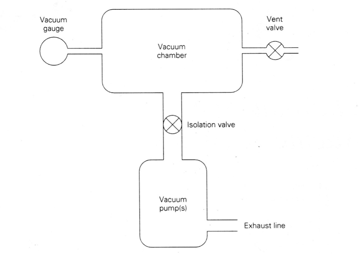
Consider the simple vacuum system shown in Figure 3.4. Suppose the conductance of the pipeline between the chamber and the pump is 400 liters/second (liters/sec) when the isolation valve is fully open. The pumping speed of the vacuum pump is 100 liters/sec. What is the net pumping speed at that moment in the chamber?
Solution:
Using Equation 3.3, we can calculate the net pumping speed:
Substituting the known values for the pipeline conductance and the pumping speed of the vacuum pump yields:
Solving for Snet,
What is the throughput in the system when the inlet pressure at the pump is 1.5 Torr and the pumping speed of the pump is 0.5 liter/sec? Assume the gas temperature is 20°C.
Solution:
Using Equation 3.2, we can calculate throughput:
Substituting the known values for pressure and pumping speed and solving for Q,
When a vacuum system’s net pumping speed for the chamber is 50 liters/sec and the gas load at the chamber is 2 x 10⁻⁴ Torr-liters/sec, what is the expected base pressure in the chamber?
Solution:
The gas load at this point in time is assumed to be equal to the throughput. Using Equation 3.2, we can calculate the base pressure in the chamber:
Substituting the known values for the pumping speed and gas load and solving for P,
3.4 Vacuum Systems – an Overview
Again, consider a simple vacuum system represented by the block diagram shown in Figure 3.4. The vacuum system consists of a vacuum chamber that is connected to a vacuum pump with an exhaust line. Between the chamber and the vacuum pump is an isolation valve to provide control when gas is being removed and when it is not. Connected to the chamber is a vacuum gauge that allows us to monitor the gas pressure in the chamber. A vent valve is also attached to the chamber so that when the isolation value is closed, the chamber can be “vented,” allowing room air to enter the chamber and return the pressure to the ambient pressure outside the chamber.
3.4.1 Vacuum Chamber
The vacuum chamber is usually the focal point in a process system. This is also true in vacuum system design. The walls of the chamber must be made thick enough to withstand the forces exerted by the atmosphere. In some cases, the chamber may be strengthened by adding additional supports, either internally or externally.
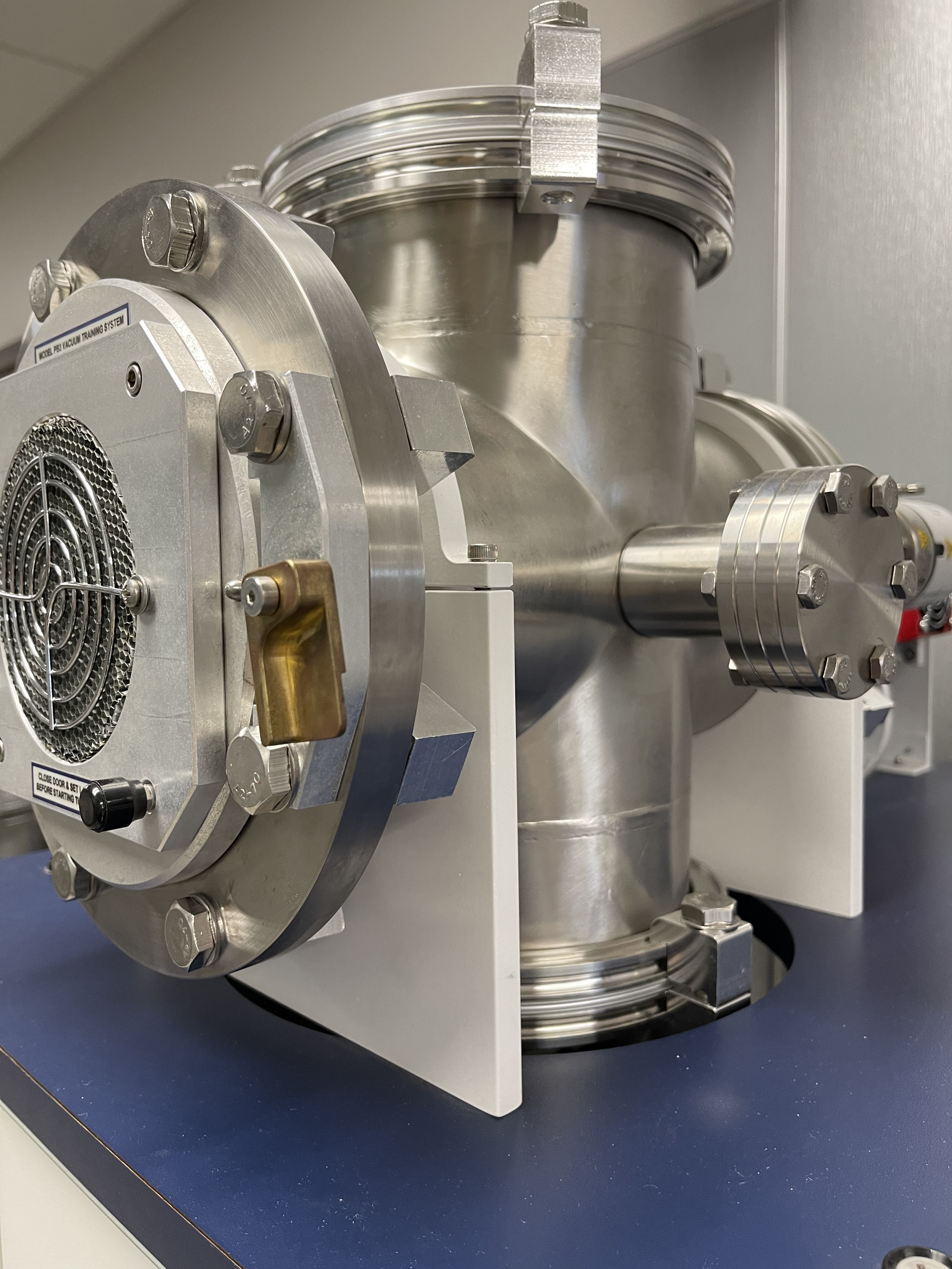
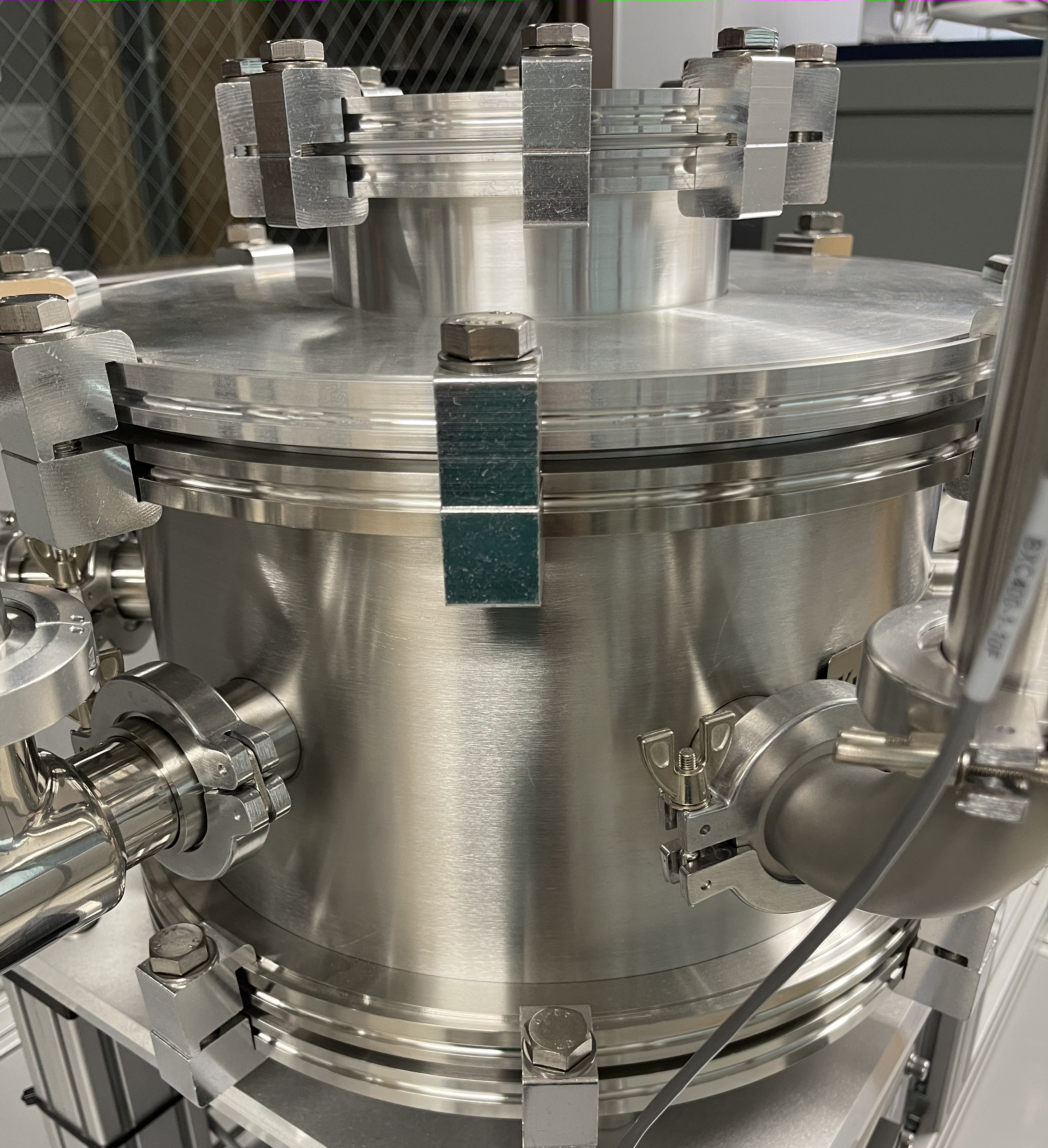
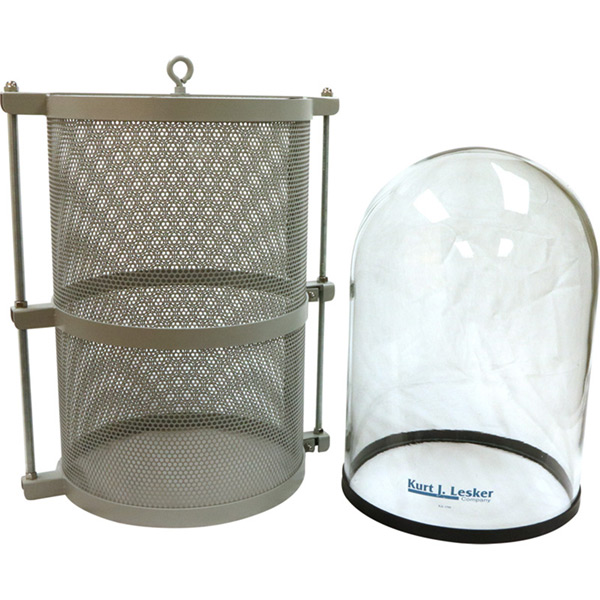
Chambers can be constructed of metal, glass, ceramic, or plastic components. Since all of these materials outgas at different rates and subsequently add to the total gas load, material selection is critical. Materials that do not bond well with water molecules and have a low vapor pressure to reduce outgassing are ideal. Plastic materials have higher vapor pressures than metals and glass. So vacuum chambers constructed from plastics cannot be used in high- and ultra-high-vacuum applications. Metals such as stainless steel and aluminum have low outgassing rates in the range of 10-6 to 10-9 Torr-liter/sec-cm2. Figure 3.5.a and Figure 3.5.b show examples of combination stainless-steel and aluminum chambers. Glass, or Pyrex, also has low outgassing rates, but these materials are not as mechanically strong as stainless steel or aluminum and need to be thicker and protected from scratching to withstand forces from the atmosphere and normal use. An example of a Pyrex chamber with protecting metal guard is shown in Figure 3.5.c. For most applications in the high-vacuum regime, permeation through the chamber walls can be considered negligible.
Estimate the gas load due to outgassing from a cylindrical chamber made of stainless steel. The chamber’s dimensions are 7.75 inches in diameter and 10 inches in height. Assume that the outgassing rate for the stainless steel is 5 x 10⁻⁸ Torr-liters/sec-cm2.
Solution:
To determine the gas load based on the outgassing rate of the stainless steel, we begin by calculating the interior surface of the chamber.
The area of the two ends of the chamber can be found as follows:
The surface area of the body of the cylindrical chamber can be found as follows:
Adding the surface areas together yields the total interior surface area of the stainless-steel chamber.
Using the total surface area and the given outgassing rate for stainless steel, we can calculate the total gas load due to outgassing by the stainless-steel chamber:
For the gas load calculated in the previous example, approximately what net pumping speed would be necessary to maintain a pressure in the chamber of 1 x 10⁻⁶ Torr?
Solution:
We will assume that the throughput in the system equals the gas load due to the outgassing of the chamber material. Using Equation 3.2, we calculate the net pumping speed needed to maintain a certain pressure as follows:
This value represents the net effect of the vacuum pump’s pumping speed combined with the system conductance.
Calculate the system’s conductance if the net pumping speed experienced at the outlet of the chamber is 110 liters/sec and the pumping speed of the vacuum pump is 150 liters/sec.
Solution:
Using equation 3.3, we can calculate conductance of the system:
To determine CPiping, take the inverse of both sides of the equation as follows:
So the conductance of the tubing which connects to a vacuum pump with a pumping speed of 150 liters/sec should be 412.5 liters/sec in order to achieve a net pumping speed of 110 liters/sec at the outlet of the chamber.
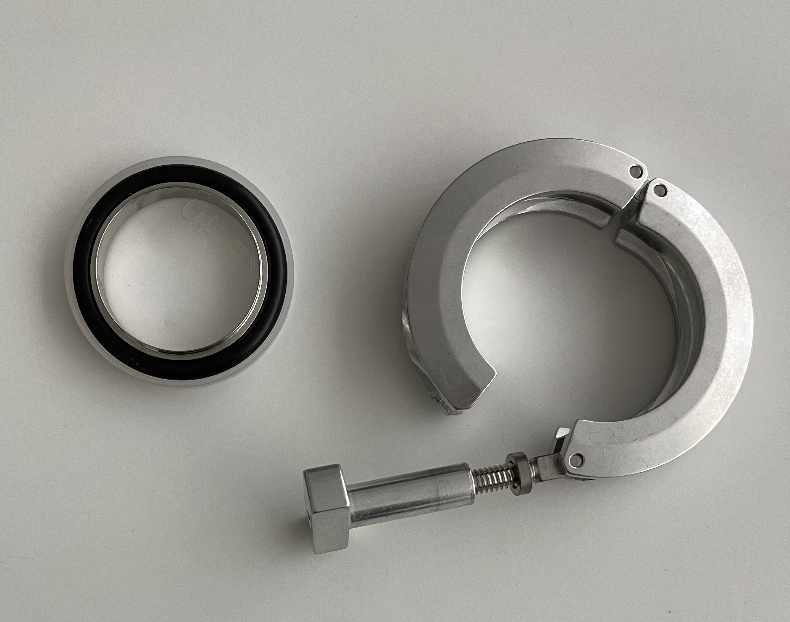
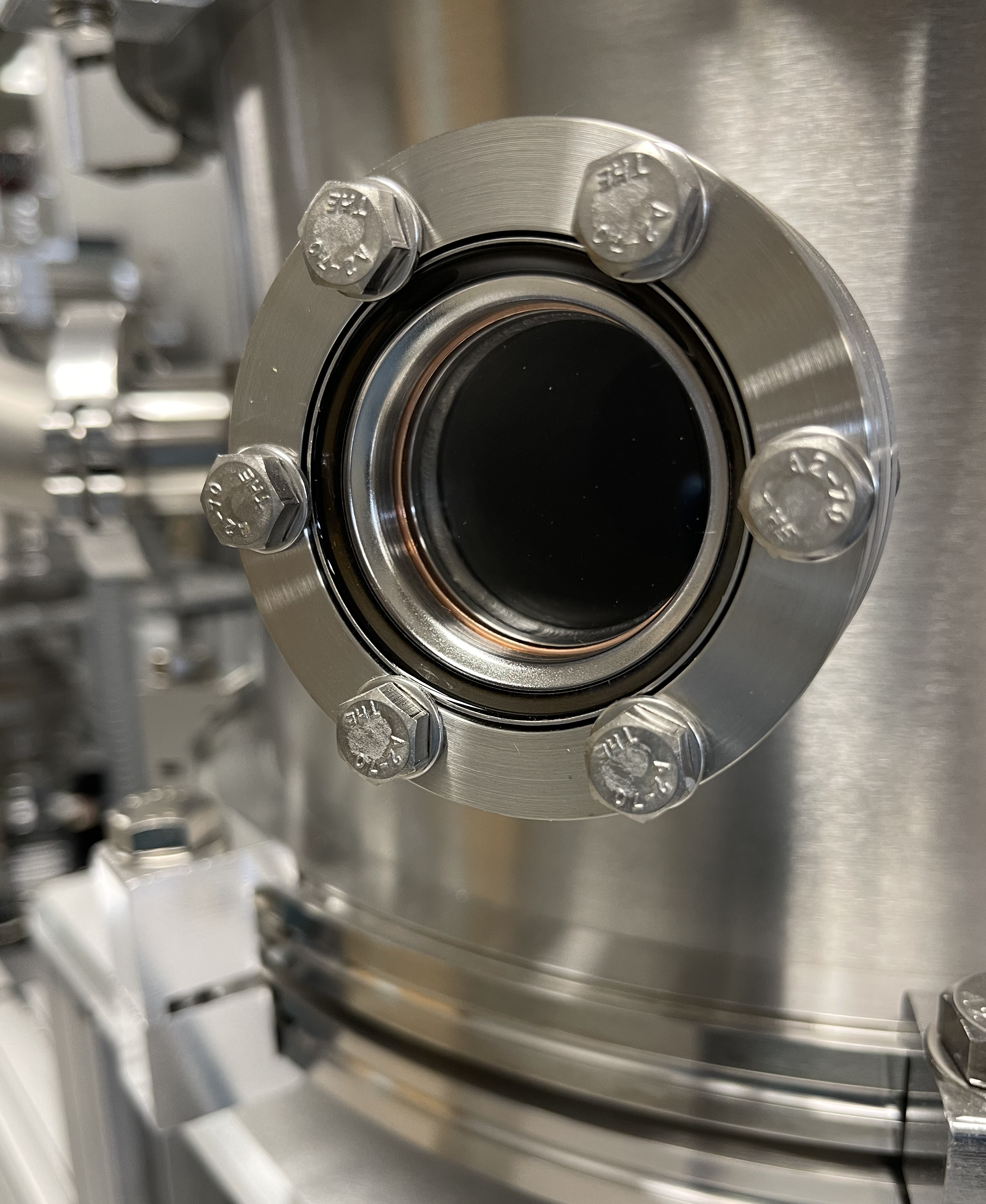
Another important consideration is the sealing material used to construct the chamber joints. If the vacuum chamber is a glass or plastic bell jar, a rubber gasket placed between the chamber and a baseplate is used to create the airtight seal. Metal vacuum chambers usually are designed with one or more ports welded to the chamber. Special welding techniques are used to insure that ports attached to the chamber do not leak. These ports are fitted with KF (Klein Flansche) or CF (ConFlat) fittings of industry-standard sizes. For KF fittings, the sealing material is an elastomer O-ring. Figure 3.6 shows an example of KF fitting and an elastomer O-ring. For CF fittings, the sealing material is a copper gasket as shown in Figure 3.7. Elastomer seals are used on joints that are intended to be demountable. The drawback to elastomer materials is that they have high vapor pressures and are much more permeable than metals. Thus, use of elastometer materials adds molecules to the gas load due to outgassing and permeation. Conversely, a metal seal, like the CF flange, has a lower outgassing rate and is not as prone to permeation. Metal seal also allows for bake out at reasonably high temperatures (> 150°C) to increase desorption rate. However, the CF flanges are more costly and difficult to attach and detach, and so they are intended for joints that will rarely be disconnected.


3.4.2 Vacuum Pumps
Vacuum pumps come in a variety of types and styles, and pump selection depends heavily on the application in which the pump is used. Figure 3.8 depicts a family tree of vacuum pumps. Although not a complete family tree, it does show the variety of vacuum pumps available. There is no one vacuum pump that alone and by itself is capable of removing gas molecules to the extent of achieving pressures across the entire vacuum regime.
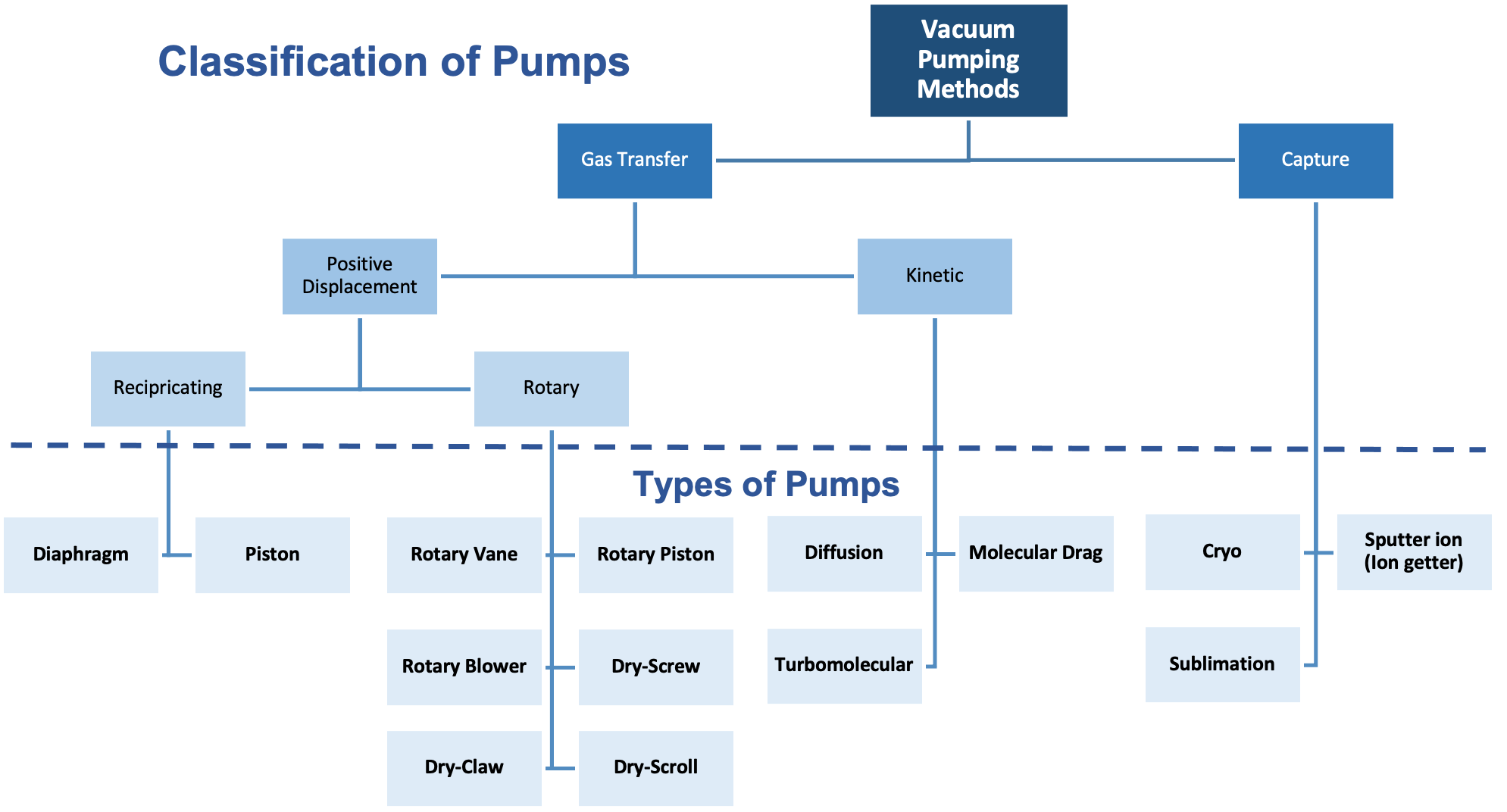
Vacuum pumps can be classified as either “gas transfer” pumps, or “capture” pumps. Gas transfer pumps remove gas from the process chamber and expel the gas into an exhaust system in the building. Gas molecules pass through a transfer pump from an inlet to the outlet. In contrast, gas molecules taken in by a capture pump are “captured” within the pump. Capture involves changing the gas molecules in the gas phase to a solid by “freezing” them or chemically reacting them with a chemically-reactive material such as titanium to form a solid compound that can stick to the interior surface of the pump. In either case, gas molecules are made immobile, so they are no longer part of the gas load.
Gas transfer pumps fall into two classifications: positive displacement vacuum pumps and kinetic vacuum pumps, also known as momentum transfer pumps. Positive displacement pumps expand the effective volume of the chamber, seal off the expanded volume, thus trapping and often compressing the trapped gas, and then exhaust the trapped gas. There are two main types of positive displacement vacuum pumps: reciprocating and rotary. Diaphragm pumps and piston pumps are examples of reciprocating pumps, whereas rotary pumps include rotary vane pumps, rotary piston pumps, and Roots pumps.
Kinetic vacuum pumps include diffusion pumps and turbomolecular pumps, or turbo pumps. A diffusion pump heats a special oil with a low vapor pressure and then forces the oil vapor at high speeds through directional nozzles. Those high-speed molecules collide with other molecules in the space. In those collisions, the high-speed oil molecules transfer their momentum to the gas molecules they strike and impart a velocity to the gas molecules, so they move in a direction away from the chamber and are expelled from the pump. Turbo pumps use high-speed turbine blades to also transfer their momentum to gas molecules and move them through the pump. Both diffusion pumps and turbo pumps require a roughing pump to expel the gas molecules from the pump and subsequently to the building’s exhaust system.
Capture pumping methods create a vacuum by condensing or freezing gas-phase molecules. Cryo pumps use this technique. Cryo pumps use very cold surfaces to freeze the gas molecules, entrapping them on the inner surfaces of the pump. Physical absorption is a technique used in cryogenic techniques. This technique uses highly porous materials, such as activated charcoal, activated alumina, and materials called zeolites, as gas sponges. The gas molecules travel into the porous structure of the material and are entrapped within the pump.
Another capture pumping technique used to create vacuum removes gas molecules from the gas load through chemical reactions. This technique is used to accomplish ultra-high vacuum conditions. For example, getter pumps use very reactive materials, such as titanium, to form solid materials from the gas molecules. These solid materials stick to the inner surfaces of the pump which effectively removes gas molecules from the gas load in the chamber as shown in Animation 3.1 and Animation 3.2.
Vacuum pumps are designed to operate over specific pressure ranges. Figure 3.9 illustrates the operating pressure ranges for different types of vacuum pumps. If the desired operating range of a vacuum system spans a wider pressure range than can be provided by one type of vacuum pump, multiple pumps can be used together and operated in a specific sequence to span the entire pressure range that is required. For example, if the operating pressure range is in the rough vacuum pressure regime from atmosphere to say, 1 Torr, mechanical pumps may be the appropriate choice as shown in Figure 3.9. But, if the desired operating pressure range extends into the high vacuum regime, a rough vacuum pump will have to be used in combination with a high-vacuum pump such as a diffusion pump or turbomolecular pump to reach an operating pressure in the high vacuum regime. In this case, the rough vacuum pump reduces the pressure to the upper operating range of the high-vacuum pump, and then the high-vacuum pump is enabled to further reduce the pressure until the desired operating pressure is reached. To reach pressures in the ultrahigh vacuum regime, three or more pumps will often have to be used.

Given the myriad of vacuum pumps on the market today, selecting the “best” vacuum pump for a specific application can be a daunting task. In many situations, there will probably be no single pump that will satisfy all process requirements. Here are some useful considerations when selecting a vacuum pump:
- What base pressure must be reached to support the process? Does the pumping speed versus pressure curve fit the process requirements?
- What is the anticipated gas load? Are there any problems associated with the gas load, for example, use of corrosive gases?
- Can the pump be installed in the intended space and with the desired orientation? Are there other considerations, such as vibration and noise that might affect its installation?
- What are the pump’s power requirements?
- Will the pump require a backing pump or other components such as valves?
- Can the pump be easily maintained? How often will the pump(s) require maintenance?
- What cleanliness level is required? Is an oil-free pump required?
- Will the process chamber be opened frequently? Is the external environment typically dry or humid? Is the external environment impacted by seasonal changes?
- What will be the cost of ownership over the period of use, not just the original purchase price?
- What is the reliability and reputation of the vendor?
This is by no means a comprehensive list of questions. Each application will have its own set of questions to consider in order to address all the issues associated with the process. The questions in this list, however, will give you a starting point in your selection process, or elimination process, as the case may be.
3.4.3 Vacuum Gauges
Measuring pressure in each regime requires converting a parameter associated with the gas molecules’ behavior which is subsequently converted into a pressure readout. There is no one gauge that alone and by itself is capable of measuring all pressures across the entire vacuum regime. Vacuum pressure gauges differ with respect to their operating pressure range, accuracy, and cost. With the exceptions of the McLeod gauge and the Bourdon gauge, all other vacuum pressure measurement devices include a transducer and the electronics to perform the conversion process and provide the pressure readout. A vacuum gauge is classified as a direct reading gauge if its measurement is based on the actual force exerted by the gas. A vacuum gauge is classified as an indirect reading gauge if the pressure is inferred from another process. Figure 3.10 shows a family tree of common pressure gauges used on vacuum systems.
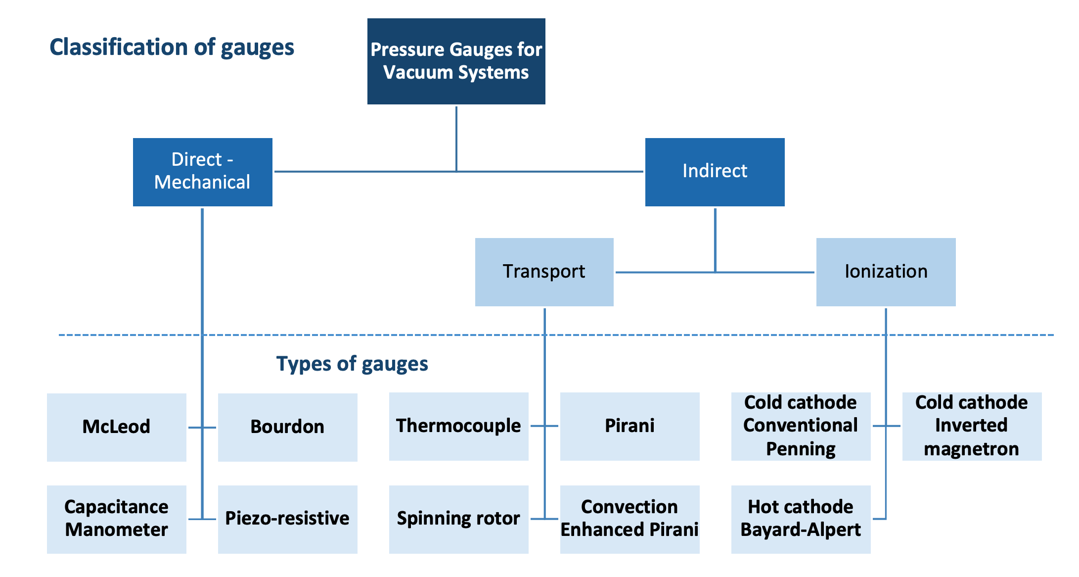
In the rough vacuum regime where the gas is relatively dense, two parameters are commonly used, the force exerted by the gas on a surface and the thermal conductivity of the gas. The McLeod gauge and the Bourdon gauge are two purely mechanical type vacuum gauges that measure pressure based directly on the force of the gas molecules present. The McLeod gauge with a design similar to a mercury manometer is capable of accurately measuring pressures of non-condensable gases as low as 10-6 Torr. The Bourdon gauge has a tube which flexes in response to pressure changes. The flexing motion actuates the mechanical movement of a needle indicator. Since the McLeod gauge and Bourdon gauge lack the electronics needed to interface to automated process systems, they are not used extensively in vacuum systems.
The capacitance diaphragm gauge is also a type of rough vacuum gauge that uses the force of the gas on a surface. There is a thin diaphragm inside the capacitance manometer. On one side of the diaphragm is a reference pressure, and on the other side is the gas in the chamber. A pressure differential causes the diaphragm to deform. The diaphragm effects the capacitance between the two electrodes on a one-sided capacitor. Since
where C is the capacitance, ε is the permittivity of the dielectric, A relates to the plate area, and d is the separation between plates, then any change in the separation caused by deformation of the diaphragm results in a change in the capacitance. The gauge controller converts this change in capacitance into an electrical signal and a pressure readout.
Similar to the capacitance diaphragm gauge, the strain gauge uses the force of the gas on a surface. This gauge is built using an insulating flexible diaphragm which supports a metallic foil pattern. On one side of the insulating diaphragm with foil is a reference pressure, and on the other side is the gas in the chamber. The difference in pressure causes the diaphragm and foil to deform. As the metallic pattern on the foil deforms, it’s electrical resistance changes. This change in electrical resistance is measured and the amount of induced stress and corresponding pressure differential can be inferred.
Examples of rough vacuum gauges that rely on the thermal conductivity of the gas are the thermocouple gauge, the Pirani gauge, and the convection enhanced Pirani gauge. The transduction process involves the transfer of heat from a filament in the gauge as the gas molecules strike the filament. Recalling the example of the Thermos in Chapter 1, as the pressure in a vacuum system decreases, heat is not transferred as readily across the space. In a thermocouple gauge operating at a constant filament power, the temperature of the filament provides an indication of the environment’s changing ability to transfer heat. This temperature change in the filament is sensed and converted to an electrical signal by a thermocouple. In the case of the Pirani gauge, the change in temperature of the filament results in a resistance change, and this resistance change is converted to an electrical signal. In a modern convection-enhanced Pirani gauge, temperature variations of the gauge surface are carefully accounted for, resulting in a gauge design that is more thermally stable, and therefore, can produce a pressure indication over a wider range.
In the high-vacuum regime, the gas is too rarefied to rely on force or thermal conductivity to measure the gas pressure. High-vacuum gauges such as the Bayard-Alpert gauge sample the pressure by ionizing gas molecules within the gauge. At the high-pressure, that is, lower vacuum, end of the operating range, a large number of ionizations occurs and results in a large current in the collector terminal of the gauge. At the low-pressure end of the operating range, fewer ionizations occur, and the resulting current in the collector is smaller. The gauge controller converts the current in the collector into a pressure readout.
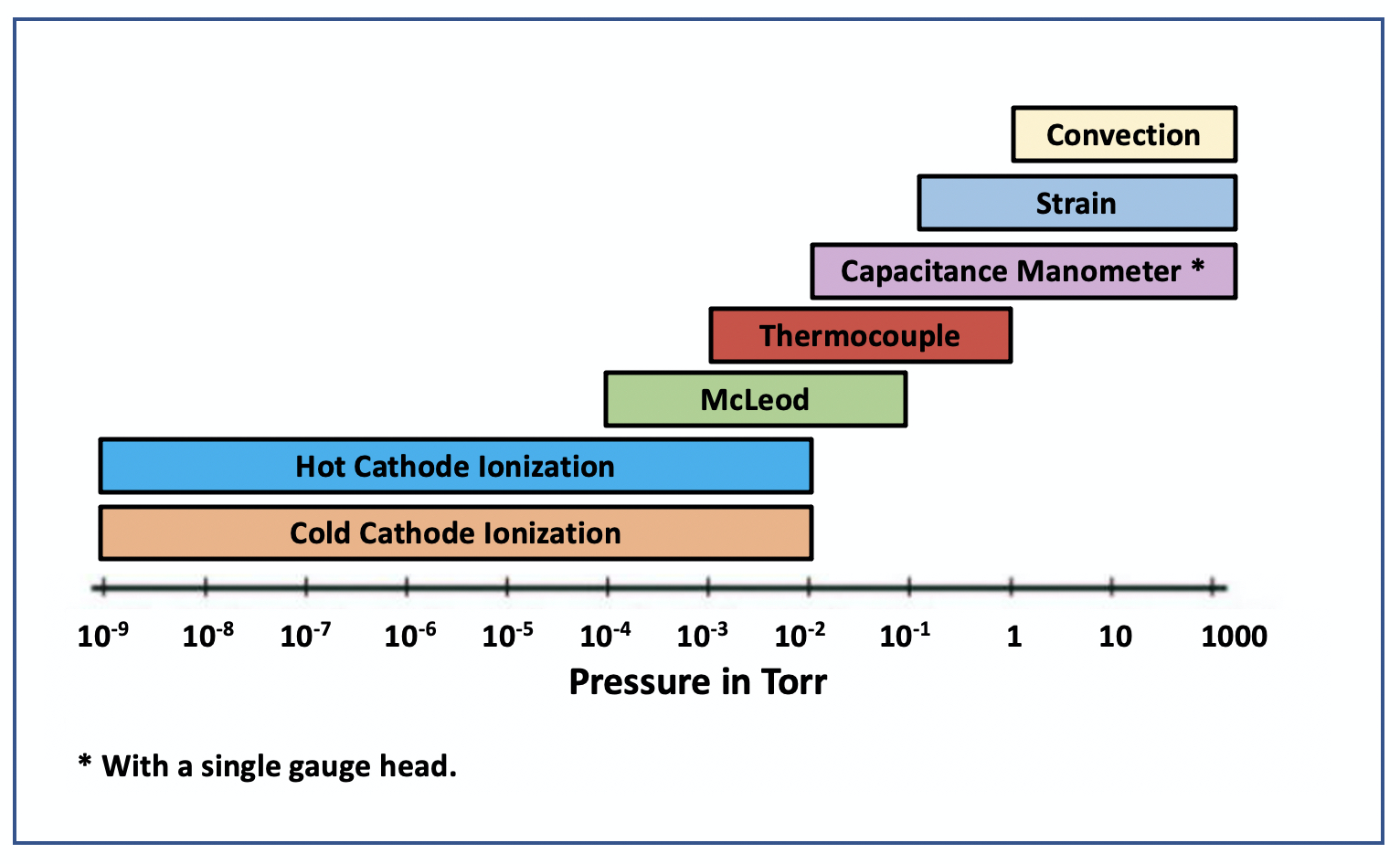
Figure 3.11 shows the typical operating ranges for common vacuum gauges. In the rough vacuum regime, convection, strain, and capacitance manometers can be used to measure pressures from atmosphere into the rough vacuum regime. However, these gauges have a lower pressure limit below which they cannot accurately measure the chamber pressure. To measure pressures into the high-vacuum regime, high-vacuum gauges must be used. When the chamber pressure decreases to the upper operating limit of the high-vacuum gauge, then the high-vacuum gauge can be turned on to measure the chamber pressure. A vacuum system which uses three gauges such as capacitance manometer, thermocouple, and hot-cathode ionization gauges to monitor chamber pressure provides a measurement of the pressure condition from atmosphere into the 10–9 Torr pressure range.
Unfortunately, measuring pressure is not merely as simple as connecting the gauge to the chamber and the gauge to the controller. A direct reading gauge yields a pressure measurement that reflects the forces exerted by the mixture of gas molecules without needing to know the underlying types of gas molecules present. However, when using indirect reading gauges, it is important to remember that gases differ in their thermal conductivity and ease of ionization. As a result, at lower pressure levels where only indirect reading gauges can be used, the readout depends on the gas composition in the chamber. Correction tables for different gases are used to correct the pressure reading presented on the readouts of gauge controllers.
Like the selection of vacuum pumps for your application, you will have a number of choices for vacuum gauges. Vacuum gauge design has come a long way in the last 20 years and new designs add convenience to pressure measurement. Here are some considerations when selecting vacuum gauges.
- Over what range must pressure be measured?
- Can the gauge accurately and safely measure the pressure of the gases in the vacuum system?
- Will the gauge require calibration and re-calibration?
- Where will the gauge be physically positioned in the vacuum system? Should the gauge include a local display?
- What is the accuracy and repeatability of the vacuum gauge?
- What is the cost of the vacuum gauge? Is it a self-contained unit, or does the transducer require a separate gauge controller?
3.4.4 Vacuum System Components
A vacuum system rarely consists of only a chamber, a pump, and a pressure gauge. Other components are needed to connect these three system components and to provide control in its operation. These additional vacuum piping components include control valves, nipples, elbows, tees, reducers, crosses, couplings, seals, flanges, and feedthroughs.
For example, a variety of valves provide vacuum systems with isolation, control, and venting capabilities. Isolation valves allow parts of the system to be isolated from other parts of the system. An isolation valve can be placed between the chamber and the vacuum pump so that the chamber can be isolated and vented to atmospheric pressure without turning off the pump. Butterfly valves and throttling valves provide a way to control conductance and thus, the flow of gas molecules in order to adjust the pressure level in the process chamber. Air admittance valves provide a way to vent the chamber or admit gas into the process chamber.
What should you consider when selecting a valve? The main factors to be aware of when selecting a valve are its operating pressure, leak-tightness, impact on conductance, and underlying outgassing rates from the materials used in the construction of the valve. Of course, there is the initial purchase price, but the functional design considerations affect the cost of ownership over the long-term operation of the vacuum system. For example, the internal geometry of the valve, depending on its placement in the vacuum system, may add to the internal surface area of the chamber. Additional surface area means more opportunity for desorption and outgassing in the vacuum system. Also, internal valve mechanisms are a source of particles and thus, contamination.
Another consideration when selecting a valve will be the materials used to manufacture it. Valve bodies are made of brass, cast aluminum, machined aluminum, or stainless steel. Brass as a material has temperature limitations, porosity and outgassing characteristics which do not support high- and ulta-high vacuum conditions. Brass components are limited to use in the foreline and roughing line of a vacuum system and to applications that do not use corrosive gases. Components constructed of aluminum and stainless steel are used in a wide variety of pressure ranges. Stainless steel has the advantage of resisting many corrosive gases.
Three common types of valves are gate, poppet, and butterfly valves. Gate values, configured with either circular or rectangular openings, provide the highest conductance. They feature a straight-through aperture. Poppet valves, also called block valves, have a seating component that is lowered into the cylindrical body to seal against a seat inside the valve. Because of their simple design, poppet valves have a long life. Poppet valves have a lower conductance than gate valves because they force the gas to make turns as the gas moves through the valve. Butterfly valves, along with throttling gate valves, are variable conductance valves that can provide a means of controlling pressure in a system.
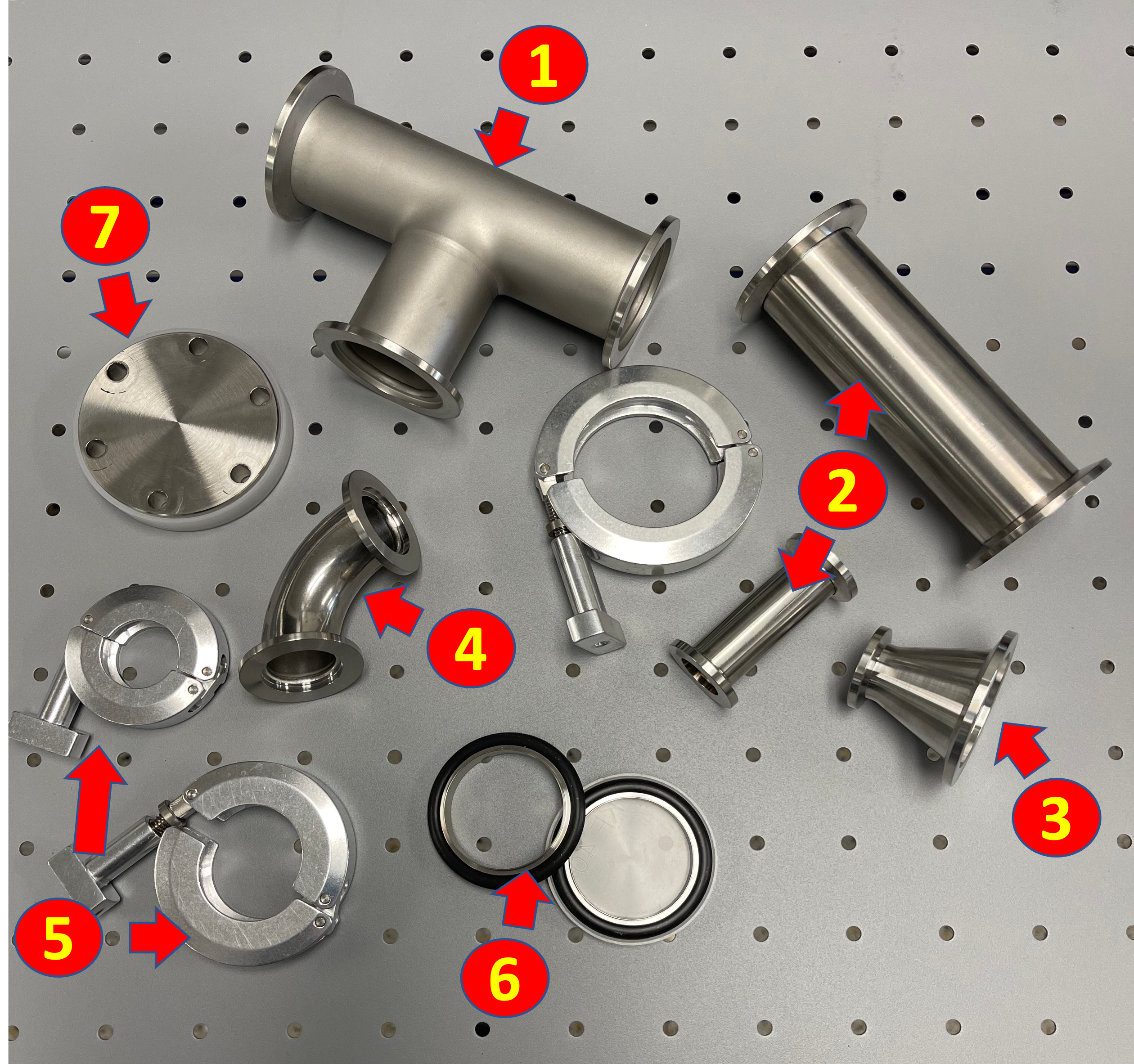
Other vacuum system components provide the plumbing to interconnect the system. These components include pipeline components (see Figure 3.12), such as nipples, elbows, tees, crosses, couplings, reducers, and adapters, and come in industry-standard sizes. The connections between these components also come in a variety of styles. The most common are the ConFlat flange (CF), the KF flange, and the ISO flange. The CF flange uses a copper gasket to form the seal, and the components to be joined are bolted together. The KF flange, on the other hand, uses an elastomer O-ring to form the seal, and when a KF clamp is used to connect two components, the elastomer O-ring is compressed in the flange. ISO flanges are used for tubing requirements that generally exceed 2-inches in outside diameter. ISO flanges are similar to KF flanges that use a centering ring with an elastomer O-ring, and use a set of single- or double-claw clamps to hold the components together.
Vacuum systems are often used to create the pressure condition necessary to carry out certain processes. In order to carry out those processes, additional energy or matter may need to be introduced into the vacuum system. Feedthroughs are leak-tight components that allow for energy or matter to be delivered into the vacuum system. For example, electrical feedthroughs deliver high voltage or high current inside the chamber space. Other feedthroughs allow liquids and gases to be introduced into the chamber space.
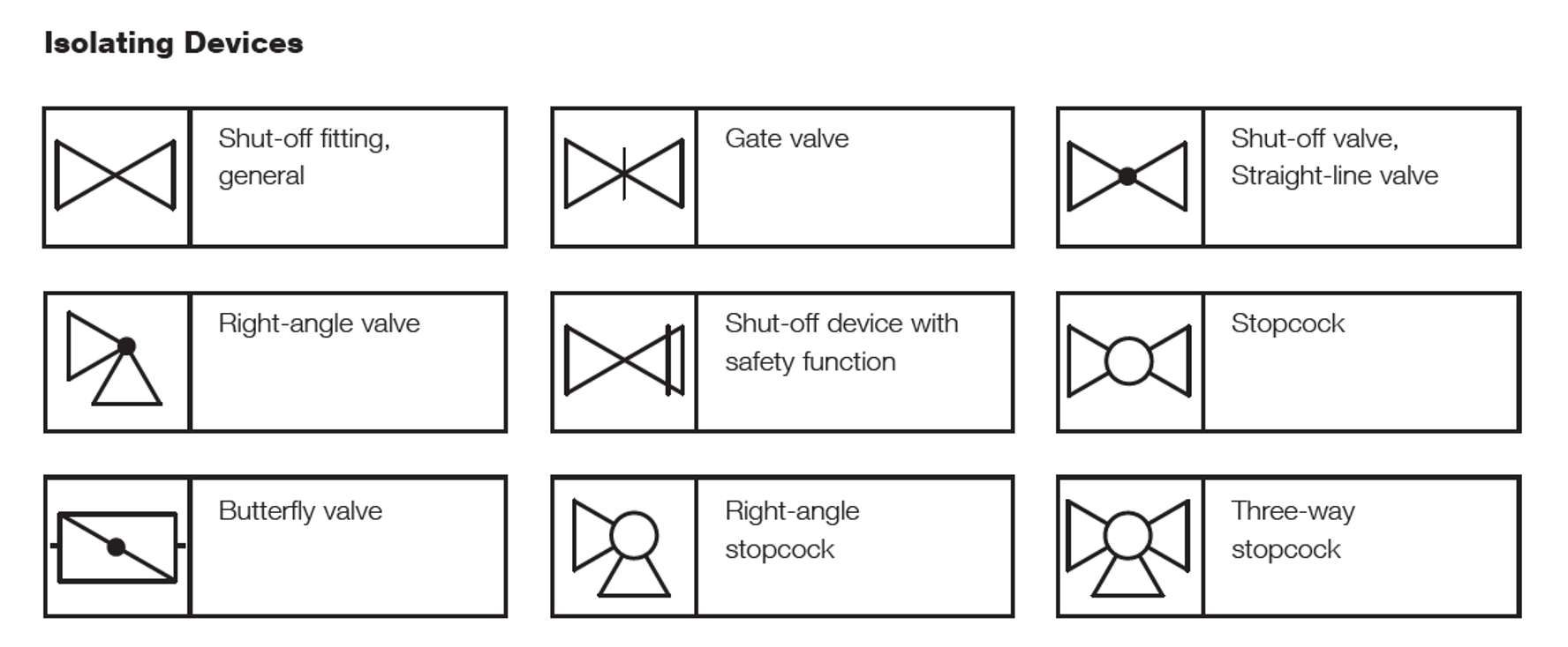
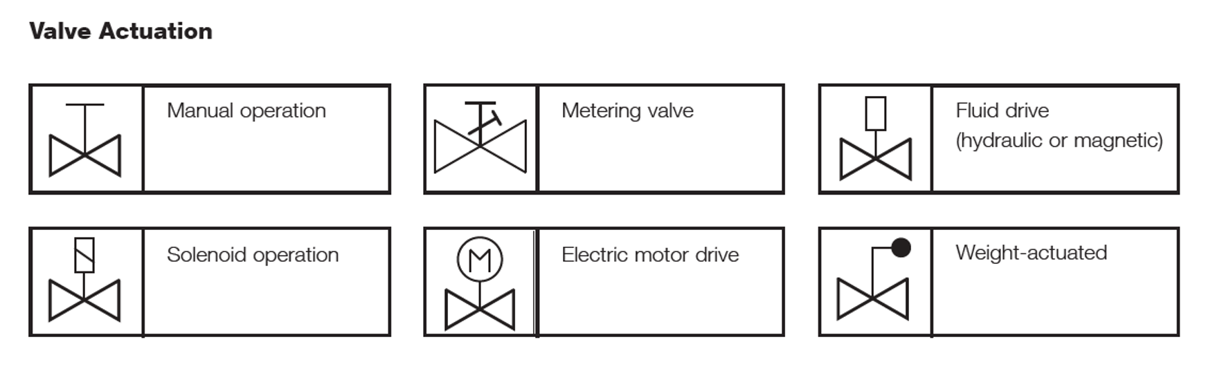
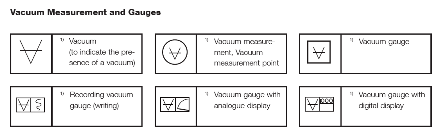
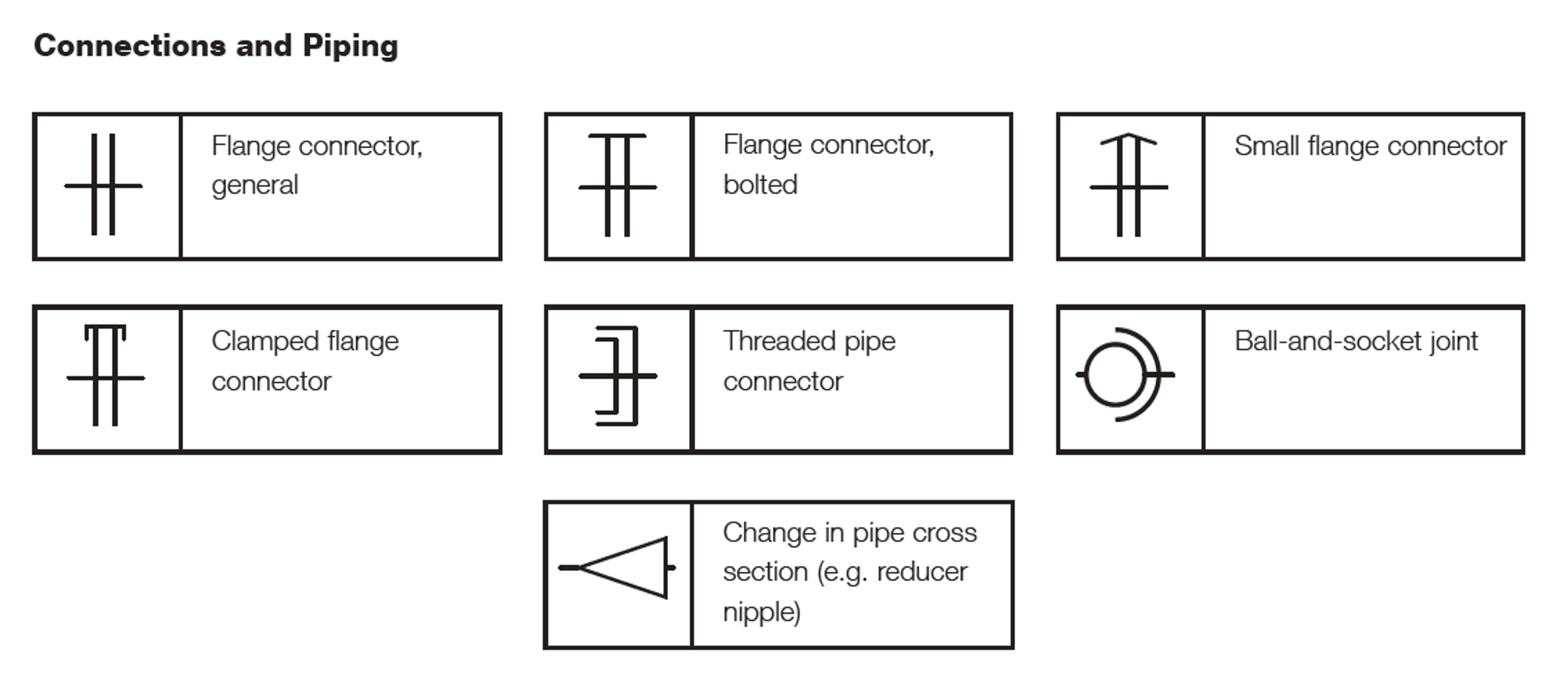
3.5 Schematic Symbols and Diagrams
Technical schematics are important documents in a manufacturing workplace. Technical schematics are a graphical representation of a complex system in a concise form that can be more easily interpreted by the reader. A technical schematic does not show the elements of a system to their actual size or scale but instead uses symbols often paired with quantitative information, like distances and electrical power, to describe the system’s configuration.
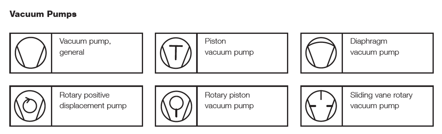
Leybold GmbH is an international manufacturer of vacuum equipment and components. Leybold compiled a listing of schematic symbols for vacuum components that can be used to create diagrams of vacuum systems. The schematic symbols fall into categories that include, but are not limited to, vacuum pumps, isolating devices such as valves, vacuum gauges, and connections and piping. Examples of schematic symbols are shown for vacuum pumps in Figure 3.13, isolating devices in Figure 3.14 (a), valve actuation in Figure 3.14 (b), vacuum gauges in Figure 3.15, and connections and piping in Figure 3.16.
3.6 A Simple Rough Vacuum System
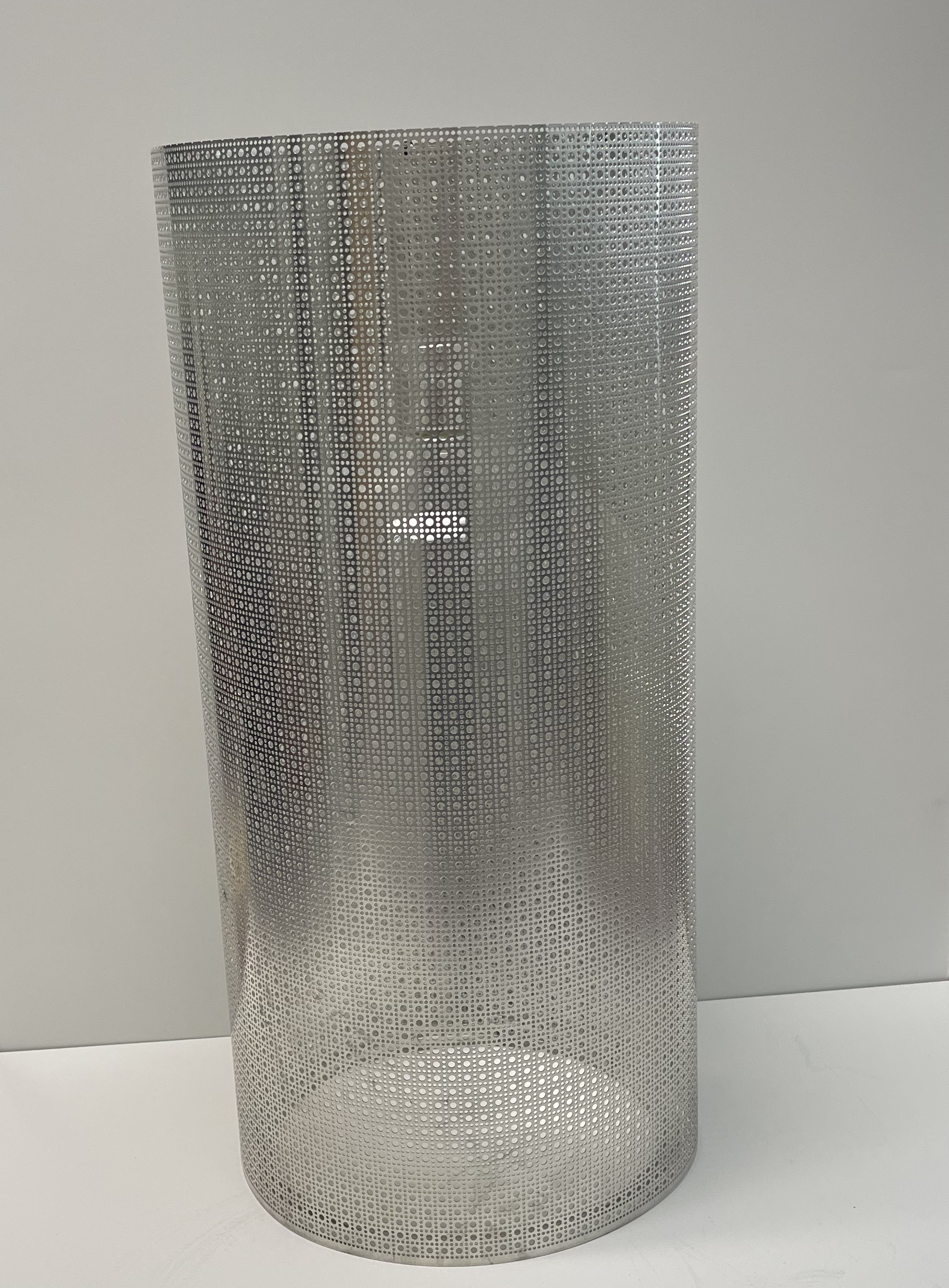
In this section, the simple rough vacuum system, shown in Figure 3.17, will be described. The system’s vacuum chamber is a Pyrex bell jar that sits on a metal base plate. In Figure 3.17, the Pyrex chamber is shown without the protective shield/guard, whereas Figure 3.18 shows the same chamber surrounded by the protective metal guard used during operation. Gas is removed from the chamber using a rough vacuum pump, in this case a scroll pump. The pump is connected to the bell jar through piping that includes a KF40 to KF16 adaptor to change the size of the piping. A manually-actuated butterfly valve is placed in the gas flow pipeline to isolate the bell jar from the vacuum pump, or to change the conductance in the roughing line. Pressure in the system is measured by a rough vacuum gauge (Convection Enhanced Pirani gauge). Finally, a vent valve provides a means to return the bell jar to atmospheric pressure. Video 3.1. provides the detailed overview of this rough vacuum system.
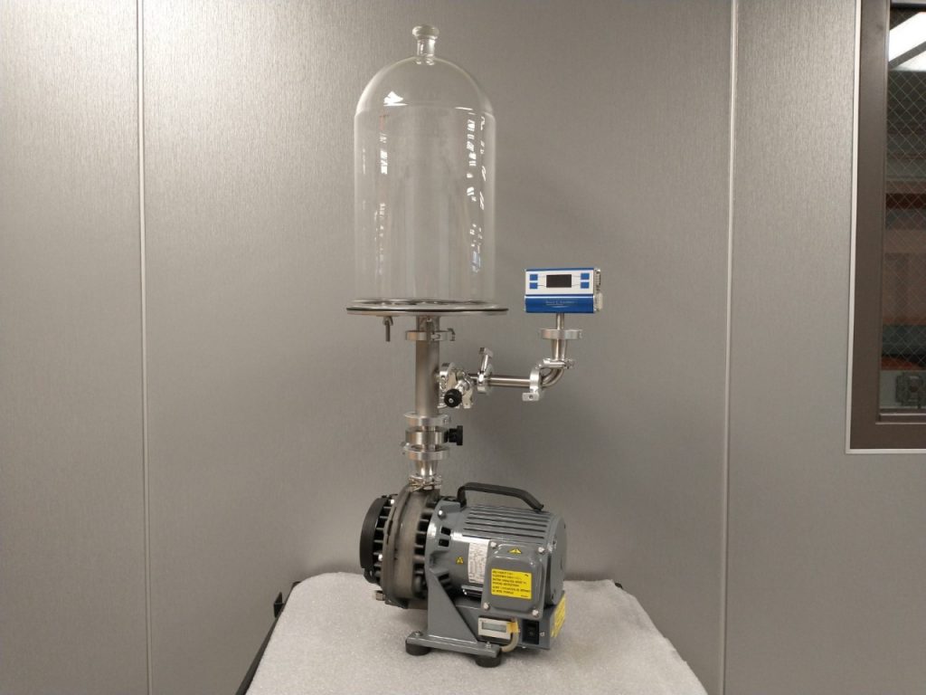
Video 3.1. Description of SUNY Erie’s rough vacuum system. Video prepared by Richard Hill and Anthony Klejna, SUNY Erie Community College.
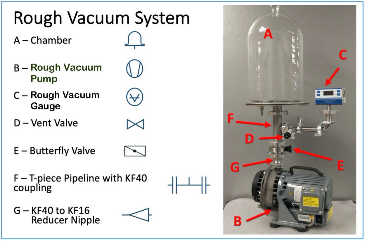
Figure 3.19 shows the location of various components in the vacuum system and the vacuum symbol that can be used to present each system component. On the left side of the figure are the main components of the rough vacuum system and the associated schematic symbol. On the right is a picture of the rough vacuum system with letters and arrows to show the location of each system component.
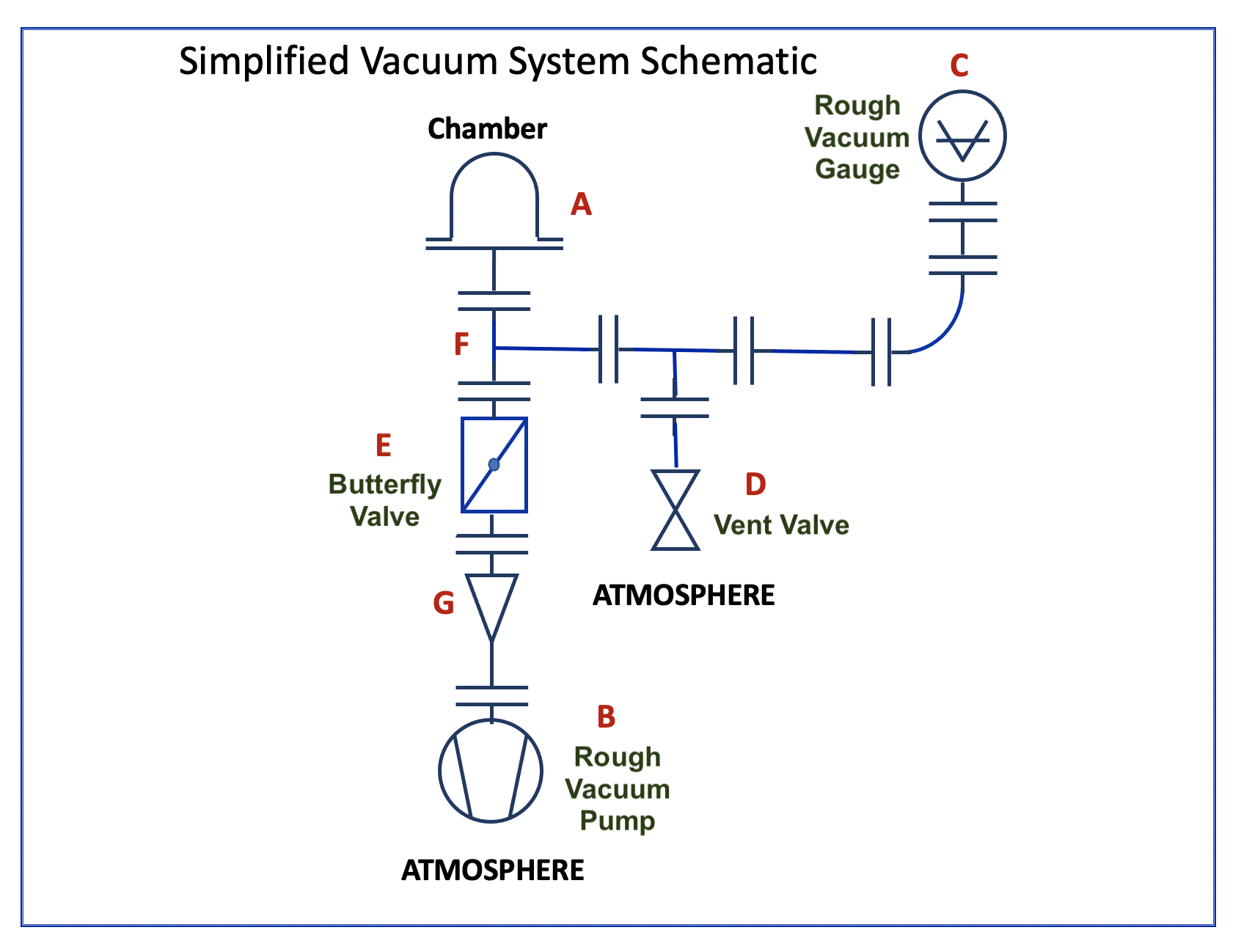
Using Leybold’s vacuum component symbols, we can then create a schematic diagram that represents the physical, rough-vacuum system shown in Figure 3.20. The schematic shows the connections between the components used to construct the rough-vacuum system and conveys the function of each vacuum component. Using the schematic diagram, you can trace the conductive pathway from the bell jar to the pump, identify the gauge used to measure pressure, and determine where valves are located to control the flow of gas in the system.
3.7 Characterizing Vacuum Systems
Knowing your vacuum system is the first step in detecting and addressing problems that occur in vacuum systems. Qualitatively, this can be as simple as hearing unusual sounds from your system, just as you might hear odd noises in your car when you start it or drive it. Unfortunately, problems in vacuum systems cannot always be detected by listening.
Another method is to keep records of vacuum system performance. For example, a system log might include the time-to-pressure or pump-down times along with base pressures recorded at establish the system’s baseline performance. This offers simple tracking data that will indicate when system performance has changed, such as when the system seems to be pumping down slower than usual or is not pumping down quite as far as it used to.
Phil Danielson, in an October 1998 article entitled “The Value of Pumpdown Curves,” describes the industry practice of using pump-down curves to characterize vacuum systems and to diagnose problems. A pump-down curve is a graph of pressure versus time that shows the performance of a vacuum system as the system is pumped down from initial pressure to base pressure. If you acquire data to create pump-down curves that correspond to optimal system operation, future pump-down curves can be compared to the optimum curve to monitor system performance. If the two curves are identical or very similar, chances are that the system is operating normally, and there is no problem. On the other hand, if the two curves differ, this can indicate that a change, and possibly a new problem, has occurred in the system and corrective action should be taken.
We will return to the use of pump-down curves and address other system diagnostic practices in later chapters.
Summary
Chapter 3 describes the general components needed to construct a rough vacuum system: a vacuum chamber, vacuum pump, vacuum gauge(s), valve(s), and fittings. The amount of gas from all sources to be removed from the system is defined as the gas load. These sources of gas include the bulk gas in the vacuum chamber, desorption of surface gas, outgassing, permeation, contamination, leaks, and backstreaming.
Vacuum pumps are used to remove gas from the chamber. Vacuum pumps come in a variety of designs and work over a limited range of gas pressures. Rough vacuum pumps are typically positive displacement pumps that trap a volume of gas, compress it, and then exhaust it from the system. High-vacuum pumps are either kinetic-type pumps, such as turbomolecular pumps, or capture pumps, such as cryogenic or cryopumps.
Vacuum gauges also come in a variety of designs. In the rough vacuum regime, gauges operate either through the force exerted by a gas on a solid wall or by sensing the loss of energy from a filament via thermal conduction by the gas molecules. In the high-vacuum regime, pressure gauges operate by ionizing gas molecules.
Parts that connect the chamber to pumps and gauges also come in a myriad of designs. Fittings include KF, CF, and ISO designs, and piping in the form of tubes, elbows, tees, and other forms. The valves used in the rough vacuum regime are typically block valves, whereas high-vacuum valves may be of the linear gate variety.
The terms “conductance” and “throughput” were introduced to describe the flow of gas through the system. Conductance is a volumetric measure of gas flow given in units of volume per unit time. Throughput describes the amount of gas moving through the pumping system and is measured in units such as Torr-liters per second.
The chapter concluded with a simple example of a rough vacuum system. On the picture of this physical system, various vacuum system components were identified using arrows and letters. Finally, a system schematic representation, using industry-accepted symbols, was created to show the interconnection of vacuum components in the rough vacuum system.
Now that we have a general sense of what makes up a vacuum system, we will turn to examining in more detail rough vacuum systems, that is, vacuum systems that reduce the chamber pressure from atmospheric pressure to approximately 1 millitorr. We will examine rough vacuum systems in terms of gas load, pumps, gauges, and system components. The next chapter will describe how to analyze rough vacuum systems and how to characterize their operation.
References
Borichevsky, Steve. Understanding Modern Vacuum Technology. Ipswich, MA, Blue Dasher, 2017.
Danielson, Phil. “Gas Loads in Vacuum Systems.” Vacuum and Thin Film, October 1998, pp. 36-39.
Danielson, Phil. “Matching Vacuum Pump to Process.” R&D Magazine, November 2001, pp. 53-55.
Danielson, Phil. “The Value of Pumpdown Curves.” Vacuum & Thin Film, October 1998, pp. 12-14.
Harris, Nigel. Modern Vacuum Practice. 3rd ed. Nigel S. Harris, 2007.
Jousten, K. Handbook of Vacuum Technology / Editied by Karly Jousten. Second, completely revised an updated edition., Wiley-VCH Verlag GmbH & Co. KGaA, 2016.
O’Hanlon, John. A User’s Guide to Vacuum Technology. 3rd ed. Hoboken, NJ, Wiley-Interscience, 2003.
Questions and Problems
-
- When referring to a vacuum system,
- Define the term “gas load.”
- In the rough vacuum regime, identify the major contributors to gas load.
- In the high-vacuum regime, identify the major contributors to gas load.
- For a rectangular chamber (25 cm long, 25 cm wide, and 40 cm high) located in Boulder, Colorado, calculate the gas load due to bulk gas. Assume that atmospheric pressure is 840 mbar at that location.
- What is the net pumping speed of a simple vacuum system in which the conductance of the piping is 300 liters/sec and the pumping speed of the pump is 600 liters/sec?
- What would be the effect of changing the pump in Problem 3 from a 600 liters/sec pump to a much larger pump having a pumping speed of 1,800 liters/sec? What percentage improvement can be achieved?
- Consider a simple system consisting of a chamber, a rough vacuum pump and a piping. If the pumping speed of the pump is 1200 liters/sec, what is the minimum conductance the piping can have to maintain the net conductance of the system at 1000 liters/sec or higher?
- Pump-down curves are used as a diagnostic tool in maintaining vacuum systems.
- What information do pump-down curves provide?
- Give an example of a problem that could be diagnosed using a pump-down curve.
- If conductance of the piping is much larger than the pumping speed of the pump, then the net pumping speed is ______ the pumping speed of the pump.
- much larger than
- larger than
- approximately equal to
- much smaller than
- Convert the pump’s pumping speed of 10 cfm to units of:
- liters/sec
- liters/min
- If the desired process pressure in the chamber is 50 x 10-5 Torr, what should the net pumping speed be to maintain the throughput of 4.0 x 10⁻⁴ Torr-liters/sec?
- List at least 4 components of the rough vacuum system.
- Consider outgassing rates of the following materials given in Table 3.1:
Table 3.1. Outgassing rates.
Material
Average Outgassing Rate (torr-liters/sec/cm2)
High density ceramic
3.0 x 10⁻⁹
Stainless steel
6.0 x 10⁻⁹
Pyrex
8 x 10⁻⁹
Copper
1.7 x 10⁻⁸
Aluminum
2.3 x 10⁻⁷
Mild steel
4.7 x 10⁻⁷
PVC
2.4 x 10⁻⁶
Brass
4.0 x 10⁻⁶
Neoprene
3.0 x 10⁻⁵
Based on these values of outgassing rates, which one of the listed materials is the least desirable for the high vacuum system? Explain.
- Calculate the gas load due to outgassing from a spherical chamber made of Pyrex. The inside radius of the chamber is 5.00 inches. Use the outgassing rate for Pyrex as 8 x 10⁻⁹ torr-liters/sec/cm2.
- What will happen to the gas load in Problem 12 if Pyrex chamber is replaced with mild steel chamber of equal size? Explain.
- To maintain the same throughput as in Problem 13, what should be the length of Pyrex chamber if its inside diameter is 10.0 inches?
- In-class group exercise: Draw schematic of the rough vacuum system shown in Figure 3.21 below.

Figure 3.21. Example of rough-vacuum pumping system.
Photo and schematics provided by Nancy Louwagie, Normandale Community College.
- When referring to a vacuum system,
![]()
This work is supported by the National Science Foundation under grant number 2000454. Any opinions, findings, and conclusions or recommendations expressed in this e-book are those of the authors and do not necessarily reflect the views of the National Science Foundation.
Media Attributions
- Figure 3.1. © John Laswell is licensed under a CC BY-NC-SA (Attribution NonCommercial ShareAlike) license
- Figure 3.2. © John Laswell is licensed under a CC BY-NC-SA (Attribution NonCommercial ShareAlike) license
- Figure 3.3. © Nancy Louwagie is licensed under a CC BY-NC-SA (Attribution NonCommercial ShareAlike) license
- Figure 3.4. © David Hata is licensed under a CC BY-NC-SA (Attribution NonCommercial ShareAlike) license
- Figure 3.5.a. © Elena Brewer is licensed under a CC BY-NC-SA (Attribution NonCommercial ShareAlike) license
- Figure 3.5.b. © Elena Brewer is licensed under a CC BY-NC-SA (Attribution NonCommercial ShareAlike) license
- Figure 3.5.c. © Kurt J. Lesker Co. is licensed under a CC BY-ND (Attribution NoDerivatives) license
- Figure 3.6. © Elena Brewer is licensed under a CC BY-NC-SA (Attribution NonCommercial ShareAlike) license
- Figure 3.7.a. © Elena Brewer is licensed under a CC BY-NC-SA (Attribution NonCommercial ShareAlike) license
- Figure 3.7.b. © Elena Brewer is licensed under a CC BY-NC-SA (Attribution NonCommercial ShareAlike) license
- Figure 3.7.c. © Elena Brewer is licensed under a CC BY-NC-SA (Attribution NonCommercial ShareAlike) license
- Figure 3.8. © Nancy Louwagie is licensed under a CC BY-NC-SA (Attribution NonCommercial ShareAlike) license
- Figure 3.9. © CNEU is licensed under a Public Domain license
- Figure 3.10. © Nancy Louwagie is licensed under a CC BY-NC-SA (Attribution NonCommercial ShareAlike) license
- Figure 3.11. © Nancy Louwagie is licensed under a CC BY-NC-SA (Attribution NonCommercial ShareAlike) license
- Figure 3.12. © Elena Brewer is licensed under a CC BY-NC-SA (Attribution NonCommercial ShareAlike) license
- Figure 3.13. © Leybold is licensed under a All Rights Reserved license
- Figure 3.14.a © Leybold is licensed under a All Rights Reserved license
- Figure 3.14.b. © Leybold is licensed under a All Rights Reserved license
- Figure 3.15. © Leybold is licensed under a All Rights Reserved license
- Figure 3.16. © Leybold is licensed under a All Rights Reserved license
- Figure 3.17. © Richard Hill is licensed under a CC BY-NC-SA (Attribution NonCommercial ShareAlike) license
- Figure 3.18. © Richard Hill is licensed under a CC BY-NC-SA (Attribution NonCommercial ShareAlike) license
- Figure 3.19. © Elena Brewer is licensed under a CC BY-NC-SA (Attribution NonCommercial ShareAlike) license
- Figure 3.20. © Elena Brewer is licensed under a CC BY-NC-SA (Attribution NonCommercial ShareAlike) license
- Figure 3.21. © Nancy Louwagie is licensed under a CC BY-NC-SA (Attribution NonCommercial ShareAlike) license
The pressure exerted typically by the Earth’s atmosphere. Also see standard atmospheric pressure and standard temperature and pressure (STP).
The average distance which a molecule travels between two successive collisions with other molecules of the gas.
The amount of gas that must be removed from the chamber in a vacuum system by the vacuum pump(s). It is typically measured in torr-liters per second, cubic feet per minute, or cubic meters per hour.
The sealed part(s) of pressure-controlled research or production apparatus where vacuum and/or other processes occur.
A vacuum component that moves gas molecules from a low-pressure region to a higher-pressure region. Vacuum-pump design is typically specific to its operating-pressure region, with the three main pressure regions being low vacuum (i.e., atmospheric pressure to ~1E-3 Torr), high vacuum (i.e., 1E-3 to1E-9 Torr), and ultra-high vacuum (i.e., less than 1E-9 Torr).
The number of molecules per unit volume of gas.
Term used to indicate molecular flow rate or mass flow rate. Identifies number of molecules flowing past a plane in a flow path. Units are in Pressure x Volume / Time (e.g., Torr-Liter/Sec).
The volume of gas that will flow past a given plane in a gas flow path in a given amount of time. Units are in volume per time (e.g., Liters per second). See also Volumetric Flow Rate.
A parameter used to represent the ease of a molecule’s flow through an obstacle based on the pressure difference on either side of the obstacle.
The volume of gas trapped within the chamber and vacuum piping components prior to initiating a pump-down cycle. Also called volume gas.
The liberation of gases and vapors sorbed (adsorbed and absorbed) by a material.
The process of gas molecules that are weakly bound to a surface, bound to pores or cracks in a material, or diffused into the bulk leaving the surface to become gas-phase molecules. Also known as surface desorption.
The process of molecular penetration of gases, vapors, or fluids completely through a material.
A mechanical gasket in a circular shape made of an elastomer with a round cross section or metal such as copper. O-ring is sandwiched between two components and blocks a path which may otherwise allow gas to escape. Essentially, they help to prevents leaks when two components are joined together.
A crack, hole, or other pathway that allows gases to pass through from outside the vacuum system to inside the vacuum system.
A volume of trapped gas that enters the vacuum system when the system is pumped down.
The volume of gas that will flow past a given plane in a gas flow path in a given amount of time. Units are in volume per time (e.g., Liters per second). See also pumping speed.
The bar is a metric unit of pressure but is not part of the International System of Units (SI). One bar is exactly equal to 100,000 Pa. The millibar (mbar) is a unit of pressure typically used to express vacuum pressures. One mbar is exactly equal to 100 Pa.
The mean volume flow through the cross section of the inlet port of a vacuum pump after the effect of all conductances have been accounted for.
Commonly used term for evacuation of a vacuum chamber from atmospheric pressure to a pre-defined base pressure.
In vacuum systems, mechanical pumps are motor-driven pumps that move gas from the inlet port to outlet port using a mechanical mechanism, e.g. rotary vanes, scrolls, pistons, and diaphragms among others.
Time required to evacuate a chamber from atmospheric to a predefined base pressure.
A tube that connects the gas outlet from a vacuum system to a building exhaust system.
A valve placed between two components, or parts of a vacuum system, that blocks the flow of gas between the two parts.
Part of a vacuum system that controls the flow of outside air (or gas) into the vacuum chamber.
Quick-release flange couplings in sizes DN 16 to DN 40, suitable for low (rough), medium and high vacuum. Elastomer gaskets and metal gaskets can alternatively be used for sealing. KF (Klein Flansche) flange is also known as KF (Klein Flansche fitting).
A type of de-mountable metal-sealed joint used in vacuum technology that supports ultra-high vacuum operation. Also known as conflat-type (CF) fitting.
Vacuum pumps that remove gas from the vacuum chamber, move it through the pump, and then exhaust the gas to the building exhaust system or into the environment.
A classification for high vacuum pumps that operate by adsorbing gas-phase molecules onto a surface or into a bulk material.
A structural state of matter in which the thermal motion of the respective molecule species near room temperature is sufficient to exceed any cohesive forces, and permit their free motion. Contrast with term vapor phase.
A classification of pump that captures a volume of gas near the inlet and mechanically displaces it to the outlet. Often compression of the captured volume occurs between the inlet and the outlet.
A vacuum pump that draws air by periodically changing the working volume of the pump.
Mechanical pump that utilizes rotary motion to drive pumping mechanism. Examples of rotary pumps are screw pump, lobe blower pump, and rotary vane pump.
A type of dry mechanical, rough vacuum pump that utilizes a movable diaphragm element to displace and compress a volume of gas from an inlet to an outlet region.
A type of positive displacement pump where the high-pressure seal reciprocates with the piston. Also called rotary piston (vacuum) pump.
A positive-displacement pump that consists of vanes mounted to a rotor that rotates inside a cavity. Invented by Charles C. Barnes in 1874.
A rotary plunger type pump where two symmetrically shaped impellors rotate in opposite directions inside the pump housing. Roots pumps are used where great volumes have to be pumped. Also known as lobe blower pump.
Kinetic vacuum pumps use various mechanisms to transfer momentum to gas molecules in order to move them toward the outlet port of the pump. Diffusion pumps use oil jets to impart momentum to gas molecules while turbomolecular pumps use high-speed turbine blades.
A high vacuum pump that uses a directed stream of heavy vapor molecules to flow gas molecules toward increasing higher pressure regions in the pump. Diffusion pump was invented in 1915 by Wolfgang Gaede.
A type of high vacuum pump that uses cold surfaces to remove gas-phase molecules by cryocondensation and/or cryosorption. Often used to refer to a vacuum pump operated with closed-cycle helium refrigeration system. Cryopump technology is based on Gifford-McMahon cryocooler which was first used to make a vacuum pump by Helix Technology Corporation in 1976.
The taking up of a gas or vapor by a solid or liquid due to physical forces in which the gas diffuses into the bulk of the solid or liquid.
A rough vacuum pump used in a vacuum system with the inlet of the rough vacuum pump connected to the outlet of a momentum transfer type-high vacuum pump. The rough vacuum pump operates to maintain an effective pressure in the foreline (also called backing line) for the expected throughput.
One of several types of electrical or mechanical devices used to measure pressure and/or gas density at various locations of a vacuum system.
A type of direct reading vacuum gauge which is used to measure very low pressures, down to 1E−6 Torr (1.33 mPa). It was invented in 1874 by Herbert McLeod.
A type of direct reading vacuum gauge with a thin-walled metal tube bent into a circular arc that will straighten if pressure is applied to the inside of the tube. The movement of the metal tube is used to indicate pressure. Bourdon gauge was invented by Eugene Bourdon (1808-1884), a brilliant French watchmaker and engineer, in 1849.
Pressure gauges that operate by sensing deflection of a solid or liquid surface caused by momentum transfer to that surface from energetic gas molecules. Direct reading gauges are largely insensitive to gas type.
Pressure gauges that measure a property related to gas pressure and then convert that measurement into a gas pressure reading.
Vacuum pressure regime with pressures between 760 Torr and 1E-3 Torr.
A type of direct reading vacuum gauge where a measurement of electrical capacitance of the diaphragm position is used to indicate pressure. Also known as capacitive gauge.
A specific type of thermal vacuum gauge where the temperature of the wire sensor is measured with a thermocouple to estimate pressure within the gauge.
A thermal conductivity pressure gauge containing a heated filament having a large temperature coefficient of resistance as an element of a resistive bridge. Because heat dissipation from the filament is a function of the gas pressure in a certain pressure range, filament resistance or power required to maintain a constant filament resistance can be correlated with gas pressure. Invented by German Physicist, Marcello Pirani (1880-1968) in 1906.
A Pirani gauge that incorporates a secondary heated wire, a compensator, which surrounds the primary heated sensor wire. Incorporating the resistance of the compensator wire serves to counteract temperature variations of the gauge body. A convection-enhanced Pirani gauge measures pressures up to atmospheric pressure and thus has a wider pressure measurement range than a basic Pirani gauge.
A type of indirect reading vacuum gauge in which a heated filament supplies free electrons at a constant controlled rate due to thermionic emission. The number of resulting ions collected in this gauge type is an indication of the total pressure present. The Bayard Alpert ion gauge is the most typical hot-filament ion gauge used.
Vacuum piping components provide pathway for the gas to flow within a vacuum system. Examples of vacuum piping components are tees, nipples, elbows, crosses, reducers, and flanges or fittings.
A vacuum component that transfers motion, electrical charge, water, light, heat, etc. into and/or out of a vacuum chamber while maintaining vacuum.
A vacuum valve that can be controlled by the operator to be only partially open (or partially closed). Allows to control pumping speed by decreasing conductance (to throttle) between a vacuum chamber and a vacuum pump.
The vacuum tube that connects the output of a high-vacuum diffusion, turbomolecular, and/or drag pump to a rough-vacuum mechanical backing pump.
Roughing a vacuum chamber indicates that it is being evacuated with a low-vacuum pump through a roughing line from atmospheric pressure to a pressure that is sufficiently low to allow a high vacuum pump to be engaged.
A valve typically used to control the timing and quantity of gas flow.
A large diameter valve usually placed between the vacuum chamber and the vacuum pumps to isolate the vacuum chamber from the pumps when it is necessary to work on something in the chamber.
A high vacuum flange that uses a metal O-ring to seal the connection between two components using either clamps or bolts.
A natural or synthetic polymeric material that demonstrates elastic properties.
Any one of the many parts that are required to construct a functioning vacuum system, or parts required to undertake and control a vacuum process.
A dry mechanical vacuum pump design that utilizes two intermeshed spirals (i.e., scrolls) to displace and compress a crescent-shaped volume of gas from an inlet to an outlet region.
A type of high-vacuum valve with a movable circular plate that is mechanically adjusted to allow varying levels of gas flow through the valve’s orifice or block gas flow altogether.
Graph describing a time-dependent pressure drop in a vacuum system; popular control instrument when designing and operating a vacuum system.
When unwanted gases like oil vapor or particles flow from downstream pumping or other components toward the vacuum chamber or process components, that is, in a direction opposite to the direction of the desired gas flow.
