Learning Activities 6.1 – 6.2: Building and Pumping Down a Rough Vacuum System
- Building a rough vacuum system from a vacuum system schematic.
- Applying appropriate cleanliness techniques when handling and assembling vacuum system components.
- Practicing proper pump-down procedures to operate a vacuum system.
- Evaluating the pump-down times for multiple cycles of vacuum system operation.
- Following proper procedures for storage of a vacuum system.
- Follow vacuum cleanliness procedures when handling vacuum system components.
- Identify vacuum system components.
- Build a rough vacuum system from a system schematic.
- Pump down a rough vacuum system.
- Follow proper vacuum system storage procedures.
Suggested Pre-lab Assignment
-
Read Chapter 3 of the Introduction to Vacuum Technology E-Book, Section 3.5, and draw schematics symbols for the following vacuum system components:
- Diaphragm vacuum pump
- Butterfly valve
- Manual operation valve actuation
- Vacuum gauge
Theoretical Background
A simple rough vacuum system used for this learning activity is described in Section 3.6 of the E-Book. Figure 1 below shows a rough vacuum system and symbols for its components. Figure 6.2 shows a system schematic for the rough vacuum system shown in Figure 6.1.
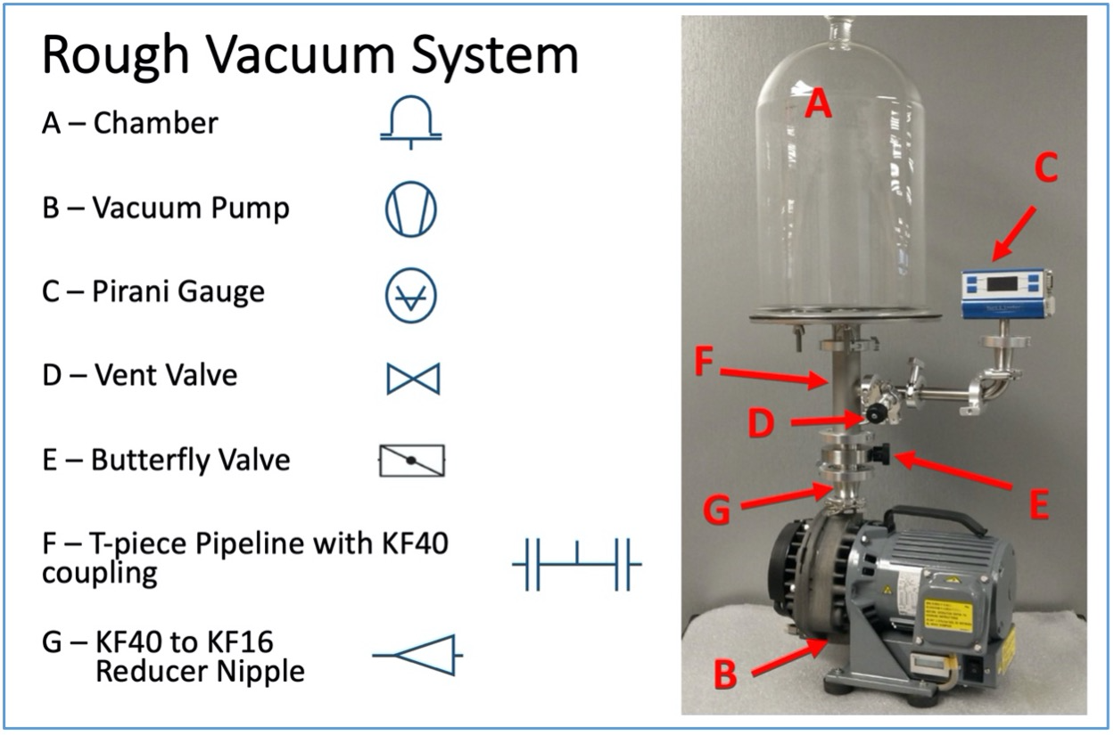
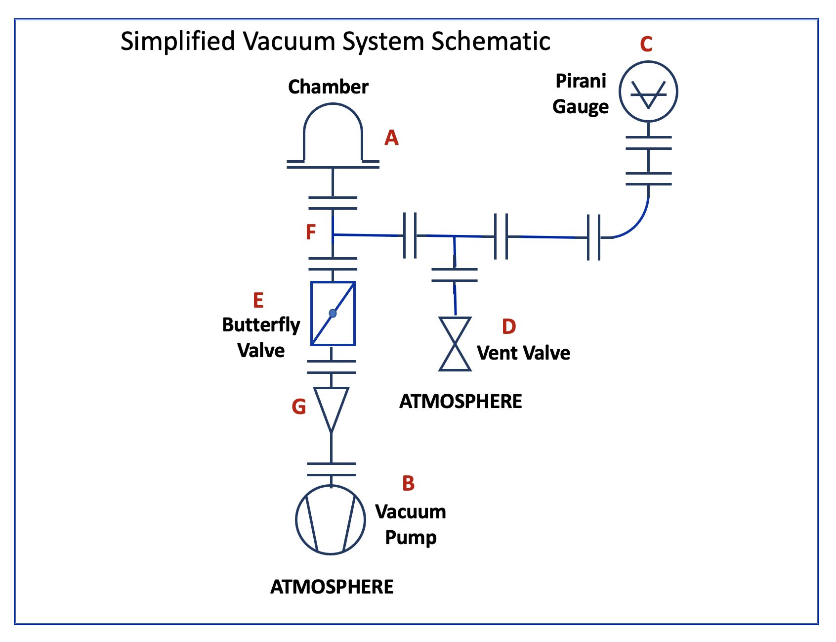
The video accessed from the link in Video 6.1 provides an overview of the rough vacuum system used for this learning activity.
Video 6.1. Description of a rough vacuum system used at SUNY Erie Community College. Video prepared by Richard Hill and Anthony Klejna, SUNY Erie Community College.
Equipment and Materials
- Vacuum system consisting of: (one each)
- Process chamber
- Absolute pressure measurement device
- Vent valve
- Isolation/roughing valve
- Vacuum piping
- Rough vacuum pump
- Nitrile Gloves (not powdered, not latex)
- Masks
- Isopropyl alcohol cleaning wipes
- Timing device
Procedure
Learning Activity 6.1: Building Rough Vacuum System
- Put on gloves and mask, making sure that you touch only the opening of rim of each glove. No oil residue from your fingers should be left on the glove surface that will come in contact with vacuum system components.
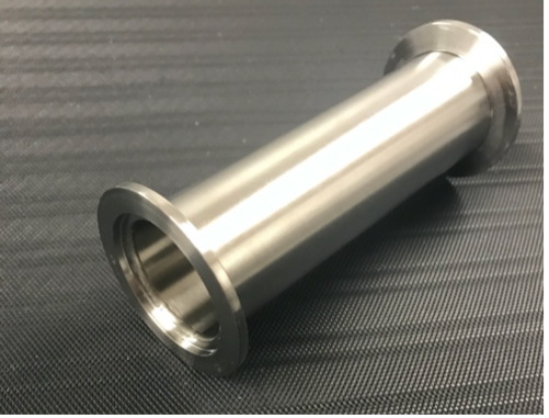
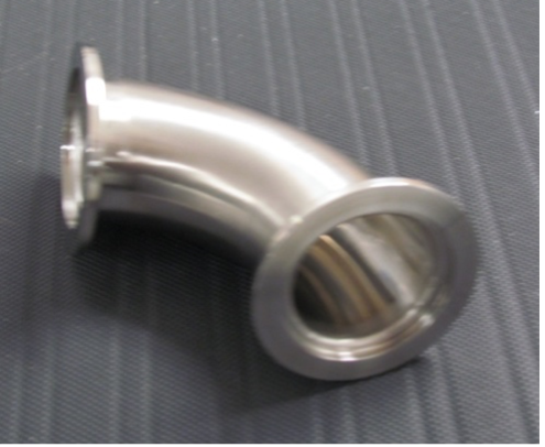
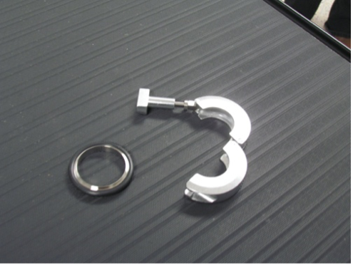
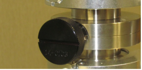
- Identify the following vacuum system components:
Pump:
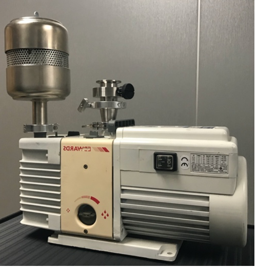
Note: The pump in Figure 6.1 is a scroll pump. The pump shown above is a rotary vane pump. Several types of rough pumps can be used in the rough vacuum system.
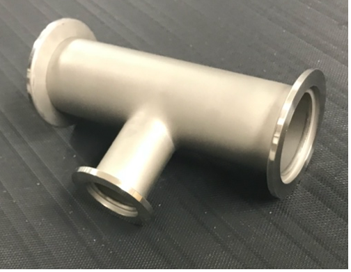
Tee:
Nipple:
Elbow:
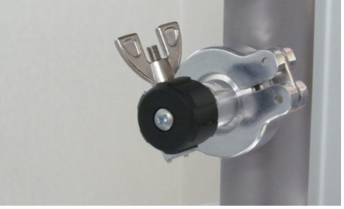
KF flange with O-ring:
Roughing (or Isolation) valve (butterfly valve is used here):
Vent valve:
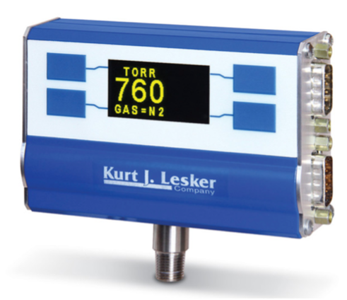
Vacuum gauge:
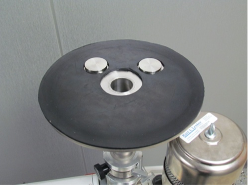
Chamber base-plate:
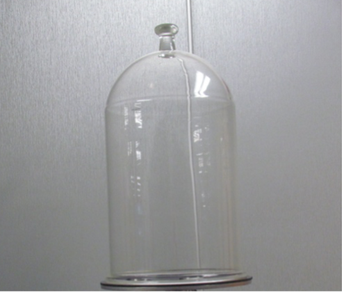
Chamber:
-
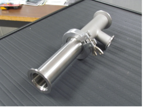
Practice assembling KF flanges with elastomer O-rings to properly connect vacuum components.
Start with two vacuum components (such as a tee and nipple), KF flange and O-ring. Wipe down the faces of the flanges and the O-ring with an isopropyl alcohol wipe.
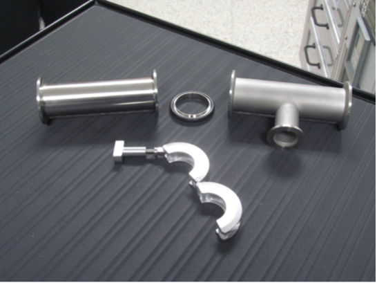
Using gloves, align the O-ring with one vacuum component and hold them with one hand:
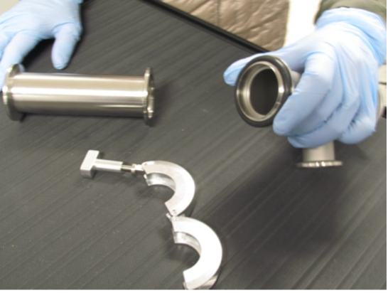
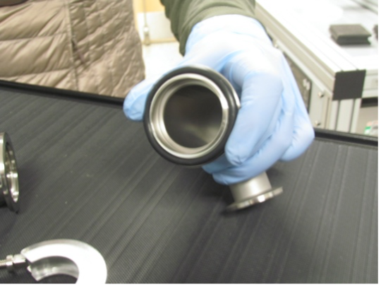
Use your other hand to align the other vacuum component with the O-ring:
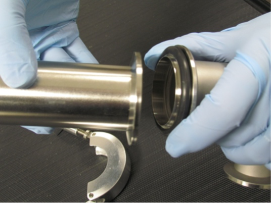
Make sure that the screw on the KF fitting is loose. With one hand hold both components aligned with the O-ring as shown in the picture and use your other hand to wrap the KF flange around the interface region.
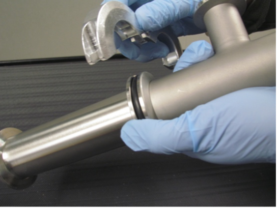
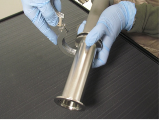
Wrap the KF flange around the interface region and thread the bolt through the grooves:
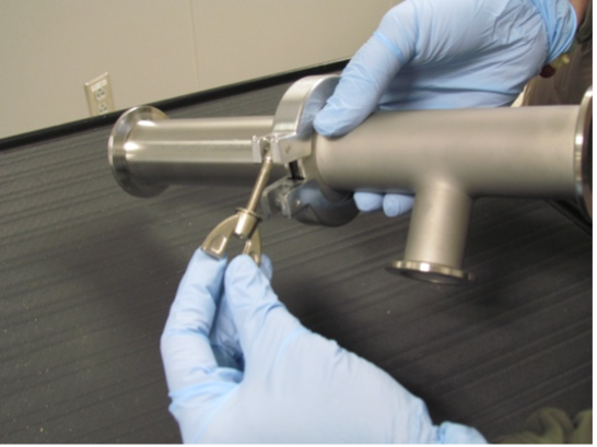
Tighten the screw:
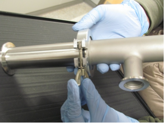
Now, the vacuum components are connected using a KF flange:
- Check the ultimate pressure of the pump by connecting a pressure gauge directly to the pump and running the pump for several seconds. Compare the measured ultimate pressure to the ultimate pressure listed on the technical specifications sheet.
- Continue this process, building the vacuum system based on the schematics provided. Start the assembly of connecting components at the pump and work towards the chamber.
Learning Activity 6.2: Pumping Down a Rough Vacuum System
- Once, the rough vacuum system is fully assembled, close the vent valve and the roughing/isolation valve.
- Turn on the vacuum gauge (if applicable).
- Start the rough vacuum pump and allow it to run for several seconds to pump down the roughing line.
- Open the roughing valve and start the timing device.
- Run the vacuum pump until the desired pressure is reached (specified by the instructor); stop the timing device.
- Close the roughing valve and then turn off the pump.
- Record the pump-down time and the final pressure in Table 6.1.
- Vent the system.
- Repeat the pump-down procedure (Steps 7 through 12) two more times to reduce the amount of contamination present in the system. For each trial, record your data in Table 6.1.
- Optional activity: remove one of the O-rings to demonstrate a real leak condition. Record data in Table 6.1.
- Optional activity: add vacuum component contaminated inside (for example, a nipple contaminated with oil from food, such as pepperoni) and repeat the pump-down procedure. Record data in Table 6.1. Make sure you remove the contaminated component before the last step.
- After the last pump-down process, pump on the empty system for several minutes to further reduce the contamination present in the system, then close the roughing valve when the system is under vacuum. Turn off the pump and the electronic pressure measurement device. Store the system under a vacuum condition.
Table 6.1. Data.
Date data collected: _________Pump-down Trial
Final pressure after pumping system down
Unit of pressure
Pump-down time
Unit of time
1
2
3
4
real leak
(optional)5
virtual leak
(optional)
Observation Notes:
Describe how the pump-down time changed between the first, second and third pump-down trials. Why?
Analysis:
N/A
Interpretation:
How do you know if there is a gross leak present in the vacuum system?
Why were several pump-down trials required after system/components were exposed to atmospheric conditions?
What will happen if you handle an O-ring without gloves?
Why do we have to use dry, not powdered, gloves?

This work is supported by the National Science Foundation under grant number ATE DUE 2000454. Any opinions, findings, and conclusions or recommendations expressed in this e-book are those of the authors and do not necessarily reflect the views of the National Science Foundation.
Media Attributions
- Figure 6.1. © E. Brewer is licensed under a CC BY-NC-SA (Attribution NonCommercial ShareAlike) license
- Figure 6.2. © E. Brewer is licensed under a CC BY-NC-SA (Attribution NonCommercial ShareAlike) license
- Pump © E. Brewer is licensed under a CC BY-NC-SA (Attribution NonCommercial ShareAlike) license
- Tee © E. Brewer is licensed under a CC BY-NC-SA (Attribution NonCommercial ShareAlike) license
- Nipple © E. Brewer is licensed under a CC BY-NC-SA (Attribution NonCommercial ShareAlike) license
- Elbow © E. Brewer is licensed under a CC BY-NC-SA (Attribution NonCommercial ShareAlike) license
- KF-flange with O-ring © E. Brewer is licensed under a CC BY-NC-SA (Attribution NonCommercial ShareAlike) license
- Roughing Valve © E. Brewer is licensed under a CC BY-NC-SA (Attribution NonCommercial ShareAlike) license
- Vent valve © E. Brewer is licensed under a CC BY-NC-SA (Attribution NonCommercial ShareAlike) license
- Vacuum gauge © E. Brewer is licensed under a CC BY-NC-SA (Attribution NonCommercial ShareAlike) license
- Chamber baseplate © E. Brewer is licensed under a CC BY-NC-SA (Attribution NonCommercial ShareAlike) license
- Chamber © E. Brewer is licensed under a CC BY-NC-SA (Attribution NonCommercial ShareAlike) license
- KF Assembly-1 © E. Brewer is licensed under a CC BY-NC-SA (Attribution NonCommercial ShareAlike) license
- KF Assembly-2 © E. Brewer is licensed under a CC BY-NC-SA (Attribution NonCommercial ShareAlike) license
- KF Assembly-3 © E. Brewer is licensed under a CC BY-NC-SA (Attribution NonCommercial ShareAlike) license
- KF Assembly-4 © E. Brewer is licensed under a CC BY-NC-SA (Attribution NonCommercial ShareAlike) license
- KF Assembly-5 © E. Brewer is licensed under a CC BY-NC-SA (Attribution NonCommercial ShareAlike) license
- KF Assembly-6 © E. Brewer is licensed under a CC BY-NC-SA (Attribution NonCommercial ShareAlike) license
- KF Assembly-7 © E. Brewer is licensed under a CC BY-NC-SA (Attribution NonCommercial ShareAlike) license
- KF Assembly-8 © E. Brewer is licensed under a CC BY-NC-SA (Attribution NonCommercial ShareAlike) license
- KF Assembly-9 © E. Brewer is licensed under a CC BY-NC-SA (Attribution NonCommercial ShareAlike) license

