Learning Activities 4.1 – 4.4: Gas Laws Activities
Learning Activities 4.1: Demonstrations of the Boyle’s Law Phenomena in Vacuum Systems
Summary of Learning Activities
Learning Activity 4.1.a: Demonstration with Expanding Glove
Learning Activity 4.1.b: Demonstration with Plastic Wrap
Learning Activity 4.1.c: Demonstration with Marshmallows
Learning Activity 4.1.d: Demonstration with Slime
Learning Activity 4.1.e: Demonstration with Plastic Bottles
Learning Activities 4.2: Demonstrations of Various Physical Phenomena in Vacuum Systems
Summary of Learning Activities
Learning Activity 4.2.a: Demonstration with Radio
Learning Activity 4.2.b: Demonstration with an Electric Fan
Learning Activities 4.3: Gas Pressure and Boyle’s Gas Law
Summary of Learning Activities
Learning Activity 4.3.a: Boyle’s Law for Expanding Marshmallow
Learning Activity 4.3.b: Boyle’s Law for Expanding Shaving Cream
Learning Activities 4.4: Gas Pressure and Amontons’ Gas Law
Learning Activities 4.1: Demonstrations of the Boyle’s Law Phenomena in Vacuum Systems
- Qualitatively investigating the relationship between changes in gas pressure and the volume the gas occupies when the prevailing temperature condition of the system remains constant (Boyle’s law).
- Utilizing a Rough Vacuum Equipment Trainer (RVET) system with a chamber to hold different objects in a space that experiences changes in pressure.
- Explain the phenomenon that relates the changes in gas pressure to the changes in the volume of the gas for a fixed amount of gas at a constant temperature when the gas is contained within a volume possessing an elastic boundary.
- Qualitatively explain the relationship between the change in gas pressure and the corresponding change of the gas volume during the RVET pump-down process (Boyle’s law).
Theoretical Background
The relationship between the volume of gas and the absolute pressure exerted by a constant amount of gas when the temperature remains constant is stated in Boyle’s law . Mathematically, Boyle’s law can be expressed as:
[latex]\begin{equation} P_1 \thinspace V_1 \thinspace = \thinspace P_2 \thinspace V_2, \end{equation}[/latex]
where P1 and V1 are the initial pressure and volume of the system and P2 and V2 are the final pressure and volume of the system. So theoretically, as long as the amount of gas and temperature do not change, the product of pressure and volume should not change. In real life under these conditions, the products of pressure and volume may not be equal for two different states due to imperfect experimental conditions such as gas leaks and/or temperature fluctuations.
The phenomenon associated with Boyle’s law can be readily observed by subjecting different objects that contain a volume of a gas within a flexible boundary to changing external air pressure conditions. As the pressure in the vacuum system decreases, the object expands (volume increases) to the point at which the pressure of the gas trapped inside the object is in equilibrium with the pressure in the chamber of the vacuum system. The learning activities described below provide different examples of how this phenomenon is demonstrated. All of these learning activities visibly demonstrate the inverse relationship between pressure and volume. An inverse relationship is characterized quantitatively as a situation in which one value increases while another value simultaneously decreases. These activities also provide qualitative insights on the types of physical conditions that impact to what extent the Boyle’s law model can be applied quantitatively in these situations.
Equipment and Materials
- Rough Vacuum Equipment Trainer (RVET) system
- Nitrile or Latex Gloves
- Bubble wrap or plastic pocket packaging material
- Marshmallows
- Slime
- Small beaker (100 ml)
- Large beaker (1,000 ml)
- Empty plastic bottle
Procedure
Learning Activity 4.1.a: Demonstration with Expanding Glove
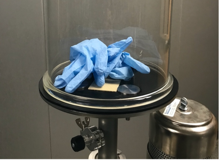
- Place a piece of metal mesh material over the opening in the vacuum system’s baseplate to prevent the expanding glove(s) from blocking the outlet that allows gas from the chamber to flow to the pump.
- Tie one end of a plastic glove to seal the glove volume. Place the glove in the chamber as shown in Figure 4.1.1.
- Before starting the pump-down process, describe how you expect the glove to behave as the pressure in the vacuum chamber decreases.
- Close the vent valve and roughing valve.
- Start the roughing pump.
- Open the roughing valve and pump the system down until the glove expands to a pre-determined volume or until the desired pressure is reached.
- Close the roughing valve.
- Why did the glove expand?
- Which gas law can be used to explain the glove’s expansion.
- Observe the behavior of the glove for 1 or 2 minutes after the roughing valve is closed. Does the volume of the glove stay the same or change?
- If the glove retains its expanded size, what does it mean for the vacuum system?
- What conditions would cause the glove to stop expanding even if the pressure in the chamber continues to decrease.
- If the glove is starting to contract, what potential problem(s) with this vacuum system might this indicate?
- Open the vent valve and observe the behavior of the glove. Explain what happens to the glove.
- Do you think that the expansion of the glove is appropriately modeled by Boyle’s law? Explain why or why not.
Learning Activity 4.1.b: Demonstration with Plastic Wrap
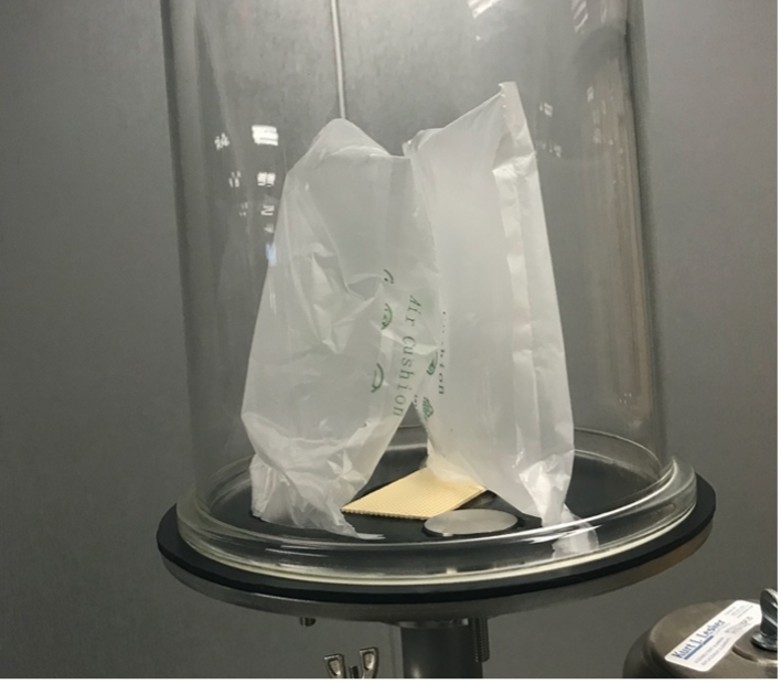
- Vent the chamber.
- Place a piece of metal mesh material over the opening in the vacuum system’s baseplate to prevent the expanding object from blocking the outlet that allows gas from the chamber to flow to the pump.
- Place the plastic bubble wrap in the chamber making sure it does not impede the gas flow to the pump as shown in Figure 4.1.2.
- Before performing the pump-down procedure, describe how you expect the bubble wrap to behave as the pressure in the vacuum chamber decreases.
- Close the vent valve and roughing valve.
- Start the pump.
- Open the roughing valve.
- Pump the system down until you see visible changes in the state of the bubble wrap or pockets. Describe your observations:
- Why do the bubbles/air pockets expand during pump-down process? Deform? Burst?
- Do you think that the expansion of the plastic packaging wrap material can be described by Boyle’s law? Explain why or why not.
Learning Activity 4.1.c: Demonstration with Marshmallows
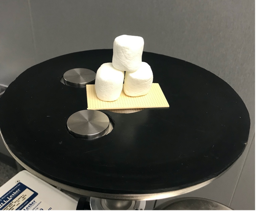
- Vent the chamber.
- Place a piece of metal mesh material over the opening in the vacuum system’s baseplate to prevent blocking the path of gas flow to the pump.
- Place the marshmallows in the chamber making sure they do not impede the gas flow to the pump (see Figure 4.1.3). A beaker can be used to hold the marshmallows.
- Before performing the pump-down procedure, describe how you expect the marshmallows to behave as the pressure in the vacuum chamber decreases.
- Close the vent valve and roughing valve.
- Start the pump.
- Open the roughing valve.
- Pump the system down and observe what happens to the marshmallows. Describe your observations:
- Explain the observed behavior of marshmallows.
- Close the roughing valve.
- Turn off the pump.
- What do you expect will happen to the marshmallows when you vent the chamber?
- Open the vent valve and observe what happens to the marshmallows. Record your observations:
- Did the marshmallows return to their original shape when the chamber was vented? Explain why or why not.
Learning Activity 4.1.d: Demonstration with Slime
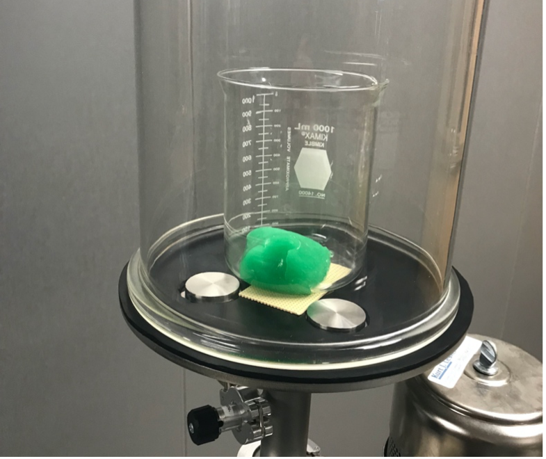
- Vent the chamber.
- Place a 1,000 ml beaker with slime in the chamber, making sure the beaker does not obstruct the opening in the vacuum system’s baseplate preventing the flow of gas out of the chamber and to the pump. See Figure 4.1.4.
- Before performing the pump-down procedure, describe how you expect the slime to behave as the pressure in the vacuum chamber decreases.
- Close the vent valve and roughing valve.
- Start the pump.
- Open the roughing valve.
- Pump the system down and observe what happens to the slime. Note: close the roughing valve before the slime expands over the top of the beaker to avoid the slime material entering into the roughing pump.
- Describe your observations:
- Close the roughing valve.
- Turn off the pump.
- What do you think will happen when we vent the chamber?
- Vent the chamber, observe the behavior of the slime, and record your observations.
- What happens to the bottles when we pump the chamber down?
- What happens to the bottles when we vent the chamber?
- Explain the differences in the behavior of bottles and behavior of bubble wrap or slime?
Learning Activity 4.1.f: Other Examples that Demonstrate the Expansion of a Volume under Vacuum Conditions
- Provide one or more examples of objects that could be used to demonstrate the expansion of a volume under vacuum conditions.
- Describe how you would expect that object to behave if you could place it in a vacuum chamber and subject it to vacuum conditions. Explain why you would expect the behavior you describe.
- Describe how you would expect that object to behave after subjecting it to vacuum conditions and then venting the system to atmosphere. Explain why you would expect the behavior you describe.
- Look for a video example on the Internet of the object you selected being subjected to vacuum conditions. Did you observe outcomes that were consistent with what you anticipated?
Learning Activities 4.2: Demonstrations of Various Physical Phenomena in Vacuum Systems
- Qualitatively investigating the effects of reduced pressure on propagation of sound.
- Qualitatively investigating the effects of reduced pressure on performance of mechanical systems such as a fan.
- Qualitatively explain how vacuum conditions affect the propagation of sound waves.
- Qualitatively explain the observed behavior of a fan operating at different pressure levels.
Theoretical Background
In a sound wave traveling in a gas, gas molecules vibrate back and forth parallel to the direction of the sound wave’s travel. In places where molecules of gas momentarily move away from each other, low pressure areas are formed. And in places where molecules of gas move closer to each other, high pressure areas are formed. Such moving consecutive segments of high and low pressures form what we call a sound wave. The key point to understand is that a sound wave requires a medium (gas, liquid, or even solid) to be able to travel. If the medium is removed, a sound wave will cease to exist. This means that sound cannot travel in an ideal vacuum. In a practical vacuum, the amount of gas molecules is reduced to the point that the intensity of the sound wave can drop below the audible level.
Another application that requires the motion of gas molecules is the operation of an electric fan. When a fan is operating at standard atmospheric pressure, it can move a substantial volume of air and produce a noticeable air flow. However, when a fan operates in a space under vacuum where enough gas molecules are removed, the fan cannot produce a noticeable air flow.
Equipment and Materials
- Rough Vacuum Equipment Trainer (RVET) system
- Nitrile or Latex Gloves
- Small battery-powered radio.
- Small battery-powered electric fan.
Procedure
- Vent the chamber.
- Place the radio (or other device) playing loud sound inside the chamber.
- Do you hear sound from the radio inside of the chamber?
- What is going to happen when we start pumping air out of the chamber?
- What is going to happen after a lot of air has been pumped out of the chamber?
- Close the vent valve and roughing valve.
- Start the roughing pump.
- Open the roughing valve.
- Pump the system down and record yout observations:
- Close the roughing valve.
- Turn off the pump.
- Can sound travel in a vacuum and why?
- Vent the system slowly and record your observations:
- Vent the chamber.
- Place a working battery-operated electric fan with loose material strips inside the chamber. Do the blades of the fan move? Do the hanging strips of cloth or plastic move? Explain why.
- Pump the system down and observe the behavior of the fan and hanging strips.
- After the pump-down process is just started, do the fan blades still move? Do the strips move? Explain why.
- After running the pump-down process for a while, do the fan blades still move? Do the strips still move? Explain why.
- Close the roughing valve and turn off the pump when pump-down process is completed.
- Vent the chamber.
Learning Activities 4.3: Gas Pressure and Boyle’s Gas Law
- Measuring the volume of two sample materials, shaving cream and marshmallows, at atmospheric pressure and a vacuum pressure level. Using pressure and volume data to verify Boyle’s law.
- Perform the pump-down sequence for the RVET system.
- Collect pressure data points from the RVET system pressure gauges and volume data points for the sample materials.
- Use scientific notation to represent numbers.
- Apply rules of significant figures (digits) through unit conversion practice.
- Calculate the percent difference between the initial and final PV products.
- Verify Boyle’s law.
Suggested Pre-lab Assignment
A sample of H2 has a gage pressure of -120.3 Torr and a volume of 155 ml. If the sample was transferred to a 1 L volume, what would the pressure be? Apply rules of significant figures to calculations.
Theoretical Background
The relationship between the absolute pressure exerted by a constant amount of gas contained in a volume with an elastic boundary is stated in Boyle’s law. Mathematically, Boyle’s law can be expressed as:
[latex]\begin{equation} P_1 V_1 = P_2 V_2 \end{equation}[/latex]
where P1 and V1 are the initial pressure and volume of an object with an elastic boundary and P2 and V2 are the final pressure and volume of that same object. Theoretically, as long as the amount of gas and temperature do not change, the product of pressure and volume should not change. In real life under these conditions, the product of pressure and volume may change slightly due to possible gas leaks from the object and/or sources of measurement error due to imperfect experiment conditions.
Equipment and Materials
- RVET system outfitted with pressure measurement gauge.
- Thermometer to measure the temperature within the chamber.
- Shaving cream.
- 2 each, jumbo marshmallows.
- Ruler with units in mm.
- 3 each, 200-milliliter (ml) beakers.
- Dry wipes.
Procedure
- Measure the dimensions of two jumbo marshmallow: height and diameter. (Note: if using marshmallows from the previous Learning Activity, use the volumes previously calculated.)
- Use a beaker with 50 ml graduated markings. Allow top of marshmallow to expand to the 200 ml level.
- Place jumbo marshmallow in the beaker with a flat side down.
- Make sure the roughing valve between the pump and the chamber is closed.
- Vent vacuum chamber to atmosphere if needed. Remove the chamber.
- Place beaker in the vacuum chamber. Place the chamber over the beaker.
- Record the temperature value Ti from the thermometer sensing the temperature inside the chamber.
- Record the pressure value P1 pressure measurement reading from the gauge.
- Shut the vent valve. Start the rough pump.
- Open the roughing valve to allow rough pump to remove air from the chamber.
- Make sure the marshmallow is expanding to occupy the full volume of the beaker out to the sides of the beaker.
- Close the roughing valve when the top of the marshmallow reaches the 200 ml marked level on the beaker.
- Record the pressure value P2 pressure measurement reading from the pressure gauge.
- Vent chamber to atmosphere.
- Remove the beaker with marshmallow from the chamber.
- Replace the marshmallow in the beaker with the second marshmallow.
- Repeat steps 4 through 13.
- Record the temperature value Tf from the thermometer sensing the temperature inside the chamber.
- Vent chamber to atmosphere.
- Remove the beaker with marshmallow from the chamber.
- After removing items from the chamber, pump system to a vacuum pressure, close the roughing valve, turn off the pump and leave the system under vacuum and unpowered.
Table 4.3.2. Data Table for Learning Activity 4.3b.
Table 4.3.2. Date data recorded:______________________
|
Data |
Value and Unit of Measure |
|---|---|
|
Starting height of the marshmallow h – Marshmallow 1 |
|
|
Starting diameter of the marshmallow D – Marshmallow 1 |
|
|
Initial volume of the marshmallow (V1) – Marshmallow 1 |
|
|
Starting height of the marshmallow h – Marshmallow 2 |
|
|
Starting diameter of the marshmallow D – Marshmallow 2 |
|
|
Initial volume of the marshmallow (V1) – Marshmallow 2 |
|
|
Initial chamber temperature (Ti) |
|
|
Starting chamber pressure – atmospheric pressure (P1) - Marshmallow 1 |
|
|
Chamber pressure when the marshmallow fills the beaker to the 200 ml mark level (P2) - Marshmallow 1 |
|
|
Pre-determined volume occupied by marshmallow (V2) - Marshmallow 1 |
200 ml |
|
Initial volume of the marshmallow (V1) - Marshmallow 2 |
|
|
Starting chamber pressure – atmospheric pressure (P1) - Marshmallow 2 |
|
|
Chamber pressure when the marshmallow fills the beaker to the 200 ml mark level (P2) - Marshmallow 2 |
|
|
Pre-determined volume occupied by marshmallow (V2) - Marshmallow 2 |
200 ml |
|
Final chamber temperature (Tf) |
|
Analysis: Verify Boyles’ Law using the Pressure and Volume Measurements for Expanding Marshmallow
Does P1V1 =P2V2?
Calculate P1V1 and P2V2. Apply rules of significant figures to the calculated results. Calculate the percent difference between P1V1 and P2V2. Are the P1V1 and P2V2 results close enough to verify Boyle’s law?
What are some reasons P1V1 and P2V2 might not be the same?
Why is the temperature measurement inside the chamber taken?
Did the different material types generate similar results? Comment on the similarities and the differences in the results.
Learning Activity 4.3.b: Boyle’s Law for Expanding Shaving Cream
-
- Apply power to the RVET system and the thermometer. Wait 30 minutes for electronic gauges to warm up.
- Record the temperature value Ti from the thermometer sensing the temperature inside the chamber.
- Record the pressure value P1 from the capacitance diaphragm gauge at atmospheric pressure.
- Add approximately 50-ml of shaving cream to the 200-ml beaker. Record the volume value V1 of the shaving cream in the beaker.
- Place the beaker with shaving cream in the vacuum chamber.
- Shut the vent valve. Make sure the roughing valve between the pump and the chamber is closed.
- Turn on the pump. Open the rouging valve between the pump and the chamber.
- Close the roughing valve when the shaving cream expands to 200 ml in the beaker.
- Record the volume value V2 of the expanded shaving cream.
- Record the pressure value P2 from the capacitance diaphragm gauge.
- Make sure the roughing valve between the pump and the chamber is closed. Turn off the pump.
- Vent the RVET system.
- Remove the beaker with shaving cream from the vacuum chamber.
- Add approximately 50-ml of shaving cream to a second 200-ml beaker. Record the volume value V1 of the shaving cream in the beaker .
- Repeat steps 4-10.
- Record the temperature value Tf from the thermometer sensing the temperature inside the chamber.
- Make sure the roughing valve between the pump and the chamber is closed. Turn off the pump.
- Vent the RVET system.
- Remove the second beaker with shaving cream from the vacuum chamber.
- Rinse the shaving cream from the beakers. Dry the beakers.
Table 4.3.1. Data Table for Learning Activity 4.3a.
Date data collected: _____________
Data
Value and Unit of Measure
Initial chamber temperature
(Ti)
Initial pressure
(P1) - 1st time
Initial volume of shaving cream
(V1) - 1st time
System pressure with shaving cream expanded
(P2) - 1st time
Volume of expanded shaving cream
(V2) - 1st time
Initial pressure
(P1) - 2nd time
Initial volume of shaving cream
(V1) - 2nd time
System pressure with shaving cream expanded
(P2) - 2nd time
Volume of expanded shaving cream
(V2) - 2nd time
Final chamber temperature
(Tf)
Analysis: Verify Boyles’ Law using the Pressure and Volume Measurements for Expanding Shaving Cream
Does P1V1 =P2V2?
Calculate P1V1 and P2V2, then say if they are the same.
Calculate percent difference between P1V1 and P2V2. Are they close enough to verify Boyle's law?
What are some reasons P1V1 and P2V2 might not be the same?
Learning Activities 4.4: Gas Pressure and Amontons’ Gas Law
- Measuring pressure of a gas at different temperatures to validate Amontons’ law.
- Collect pressure and temperature measurement data.
- Verify Amontons’ law.
- Report calculated values with appropriate significant figures.
Theoretical Background
The relationship between the temperature of gas and the absolute pressure exerted by a constant amount of gas is stated in Amontons’ law (Gay-Lussac’s law). Mathematically, Amontons’ law can be expressed as:
[latex]\begin{equation} \frac {P_1}{T_1} = \frac {P_2}{T_2} \end{equation}[/latex]
where P1 and T1 are the initial pressure and absolute temperature of the system and P2 and T2 are final pressure and absolute temperature of the system. So theoretically, as long as the amount of gas and volume do not change, the ratio of pressure over temperature should not change. In real life under these conditions, the ratios of pressure over temperature will not be exactly equal for changing conditions due to possible gauge reading errors, limitations of the apparatus set up, or gas leaks.
Equipment and Materials
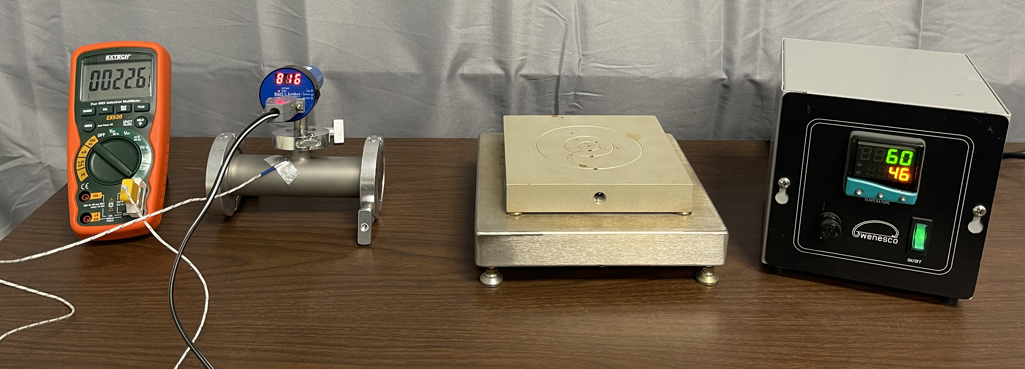
- Closed metal vessel with a fixed volume.
- Hot plate.
- Pressure measurement gauge connected to the fixed volume vessel.
- Thermocouple thermometer.
Procedure
- Preheat hot plate to up to 158°F (about 70°C).
- Apply power to the pressure gauge.
- Wait for the measurement value reflected on the pressure gauge to stabilize.
- In Table 4.4.1, record the pressure value in the closed metal vessel from the pressure measurement gauge.
- Connect the thermometer measuring unit. Wait for the measurement value reflected on the thermometer to stabilize.
- In Table 4.4.1, record the temperature using the thermometer to reflect room temperature in the closed metal vessel.
- Place the closed metal vessel on a pre-heated hot plate.
- Allow the temperature of the vessel to increase to a level of 90 - 115°F (32.2 – 46.1°C). You may want to change the orientation of the vessel on the hot plate periodically to insure more uniform heating. See Figure 4.4.2. Wait for the pressure and temperature measurement values reflected on the measuring devices to stabilize.
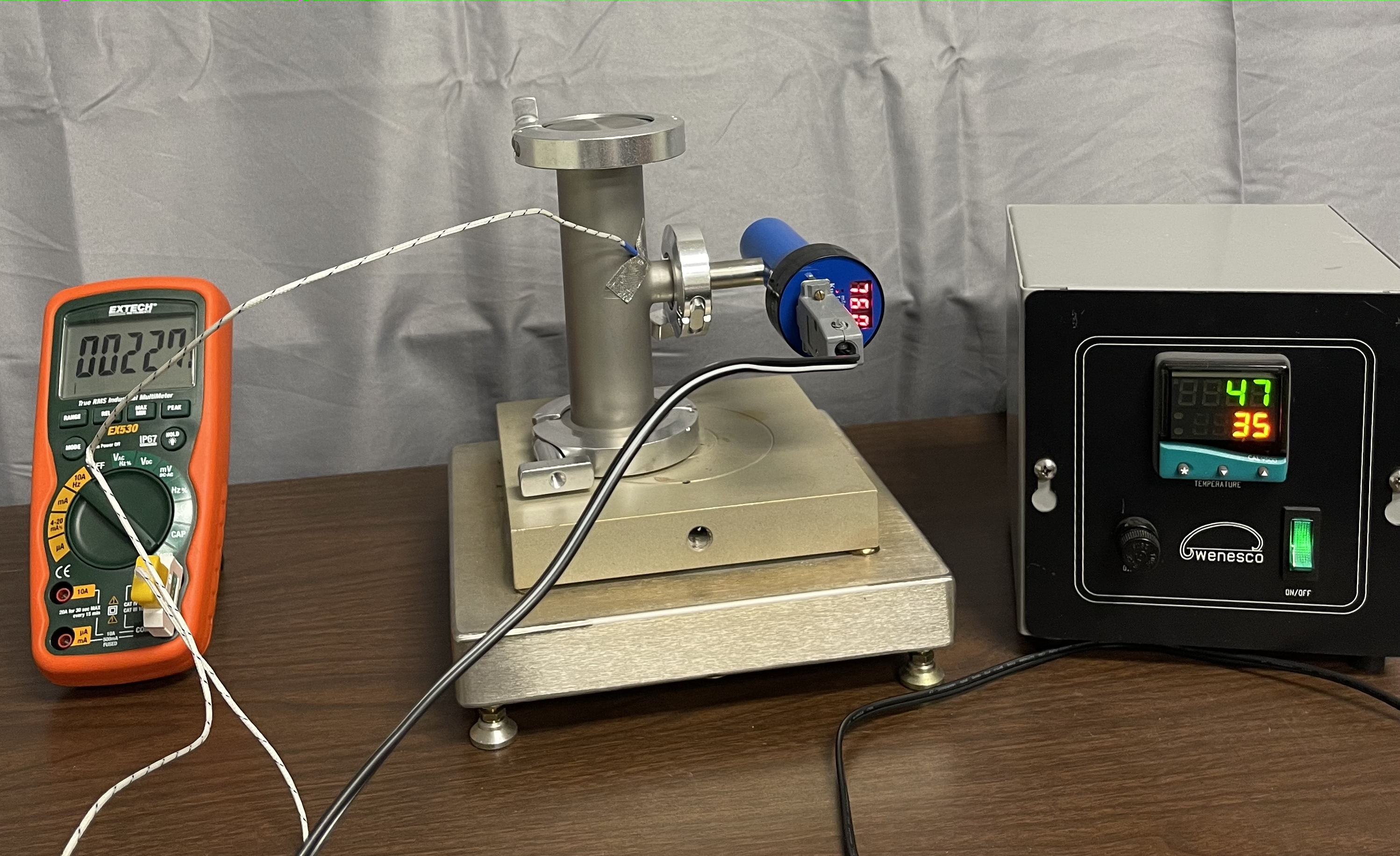
Figure 4.4.2. Different orientations of the vessel on the hot plate. Photo is provided by E. Brewer, SUNY Erie Community College. - In Table 4.4.1, simultaneously record the pressure from the pressure gauge and temperature using the thermometer.
- Turn off the hot plate.
- Let the temperature of the vessel drop approximately 5°F (2.8°C).
- In Table 4.4.1, simultaneously record the pressure from the pressure gauge and temperature using the thermometer when the temperature has decreased by 5°F (2.8°C).
- Remove power from the pressure gauge.
Name: _______________________ Date: ___________________
Table 4.4.1. Amonton's Law Data
|
Measurement |
Pressure (Torr) |
Temperature (°F) |
Temperature (°C) |
|---|---|---|---|
|
Initial P1, T1 (STEP 4 and STEP 6) |
|
|
|
|
Initial P2, T2 (STEP 9) |
|
|
|
|
Initial P3, T3 (STEP 12) |
|
|
|
Analysis of Results
- Convert each measured temperature value to Kelvin and record in Table 4.4.2.
- Calculate the ratio of P/T for the measurement values obtained in Steps 4 and 6. Be sure to use the temperature value reflecting units of Kelvin when calculating P/T. Report the calculated value with the appropriate number of significant figures. Record the result in Table 4.4.2.
- Calculate the ratios of P/T for the measurement values obtained in Steps 9 and 12. Report the calculated values with the appropriate number of significant figures. Record the results in Table 4.4.2.
- Calculate the percentage difference between the P/T ratios. Record the results in Table 4.4.2.
Table 4.4.2. Amonton's Law Calculations
Measurement
Pressure
(Torr)
Temperature
(K)
P/T
(Torr/K)
% Difference
(%)
Initial
(STEP 4 and STEP 6)
N/A
Second
(STEP 9)
Third
(STEP 12)
How well does the measured data fit with the model of Amontons’ law? Does P1 /T1 = P2 /T2? What could be some limitations to both sides of the equation being equal?

This work is supported by the National Science Foundation under grant number ATE DUE 2000454. Any opinions, findings, and conclusions or recommendations expressed in this e-book are those of the authors and do not necessarily reflect the views of the National Science Foundation.
Media Attributions
- Figure 4.1.1. © E. Brewer is licensed under a CC BY-NC-SA (Attribution NonCommercial ShareAlike) license
- Figure 4.1.2. © E. Brewer is licensed under a CC BY-NC-SA (Attribution NonCommercial ShareAlike) license
- Figure 4.1.3. © E. Brewer is licensed under a CC BY-NC-SA (Attribution NonCommercial ShareAlike) license
- Figure 4.1.4. © E. Brewer is licensed under a CC BY-NC-SA (Attribution NonCommercial ShareAlike) license
- Figure 4.4.1. © E. Brewer. is licensed under a CC BY-NC-SA (Attribution NonCommercial ShareAlike) license
- Figure 4.4.2. © E. Brewer is licensed under a CC BY-NC-SA (Attribution NonCommercial ShareAlike) license

